background image

9-32

A-61139  March 2000

Replacing the ink
cartridge

Replace the ink cartridge when any of the following conditions occur.

  When the rubber ink bladder appears shrunken or deflated.

  When the printed characters appear light or uneven.

  When missing characters are evident.

  When a print test reveals inconsistent character quality.

  When the cleaning and priming procedure has not improved the

overall print quality.

To replace the ink cartridge, perform the following procedure.

1.  Open the front cover.

2.  Note the current location of the Document Printer, then lift it from the

transport plate.

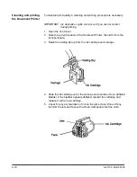
3.  Raise the holding bar up from the ink cartridge and carriage.

4.  Slide the ink cartridge out of the carriage.

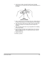
5.  Replace the old cartridge with a new cartridge by sliding a new ink

cartridge into the carriage.

6.  Lower the holding bar back down over the cartridge to hold it in place.

7.  Insert the Document Printer into its original location in the transport

plate (or a different location, if the plastic tape has been removed
from the printer slot).

8.  Close the front cover.

9.  Perform a print test.

Summary of Contents for Digital Science 9520

Page 1: ...User s Guide A 61139 Part No 1E8148 Document Scanner 9520 ...

Page 2: ...al This will ensure you of many hours of trouble free operation Your new document scanner includes a number of features these vary depending on the configuration you purchased optional features include Bar Code Reader Document Printer front and or rear Patch Reader Footswitch Workstation Endorser Please contact Kodak or your scanner vendor for more information about how these options might fit int...

Page 3: ...rührung vermeiden ATTENZIONE Superficie molto calda evitare il contatto ATENd O Superftcie quente Evite contato PRECAUCIÎN Superficie caliente No Tocar LET OP Heet oppervlak contact vermijden For the Kodak Digital Science Automatic Document Feeder CAUTION Moving parts avoid contact ATTENTION Eviter le contact pieces en mouvement VORSICHT Bewegliche Teile berührung vermeiden ATTENZIONE Parti in mov...

Page 4: ...ationsverordnung 3 GSGV Der arbeitsplatzbezogene Emissionswert beträgt 70 dB A Machine Noise Information Ordinance 3 GSGV The operator position noise emission value is 70 dB A This equipment was designed for connection to IT Power Systems ...

Page 5: ...emi automatic feeder Scans 160 landscape A4 size or 120 portrait 8 x 11 inch documents per minute at 200 dpi or 107 landscape A4 size or 80 portrait 8 x 11 inch documents per minute at 300 dpi Handles documents of up to 2 5 to 30 in 64 to 508 mm long 2 5 to 12 in 64 to 305 mm wide and 0 014 in 0 36 mm thick When using the semi automatic feeder the gap release feature allows thicker documents to be...

Page 6: ...pability A Bar Code Reader for decoding encoded information Scanner options The following options are available for use with your scanner A choice of feeders e g an optional check feeder semi automatic document feeder or automatic document feeder A choice of exit hoppers e g an optional check stacker A choice of printers the Document Printer 1 or the Super 12 Document Printer A 600 dpi 12 characte...

Page 7: ...rt area Exit hopper collects documents after they have been scanned Right side access door provides access to the transport system components Side panel switch allows you to turn the transport system on and off Gap release lever allows you to open the feed gap to allow thicker documents to be fed into the transport Gap adjustment knob semi automatic feeder only allows you to manually adjust the sp...

Page 8: ...terface Configures the scanner and runs diagnostics Computer interface 2 COIN2 bar code interface Transfers commands between the scanner and external devices subsystems Computer interface 3 COIN3 SCSI diagnostic port interface System debugging and monitoring SCSI host computer communications SCSI ports SCSI connection for the scanner Power cord plugs into an appropriate power outlet Main power swi...

Page 9: ...2000 1 5 Status display indicates the image address scan mode document level and operator messages Two line status display Image address Mode name number Scan mode indicator Document level indicator Operator message ...

Page 10: ...s display Enter an alphanumeric character in the image address Down arrow The Down arrow allows you to Decrement values at a faster rate Decrease a data value when used with certain functions Enter an alpha character in the image address fixed field Plus key Inputs a value for the image address When pressed it allows a field to remain unchanged Right arrow The Right arrow allows you to Increment v...

Page 11: ...tion Jog Momentarily turns on jogs the transport system to help clear document jams Keys Indicators Function Numeric keys 0 9 Enter numeric data such as an image address or function code F key Selects one of the available functions when used with the numeric keys Decimal key Inserts a field separator in an image address Level 1 key Identifies the next document fed into the scanner as a Level 1 doc...

Page 12: ...dress change Confirmation tone alarm The confirmation tone alarm is located under the control panel and sounds when one of the following conditions occur Run is pressed one long tone Stop or End is pressed many short tones followed by a long tone Feeder clutch engages disengages one short tone Incorrect key is pressed three short tones When using skew detection and the document skew is greater tha...

Page 13: ...e documents for scanning Turning on the scanner Follow the steps below to turn on the power to the scanner 1 Turn on the main power switch located at the rear of the scanner NOTE It is not necessary to turn off the main power switch during normal daily operations 2 Turn on the side panel switch Wait until the status display indicators are lit and an operating display appears before you continue Se...

Page 14: ...nish not glossy White or the same color as the background color of the documents to be scanned If you are scanning a variety of colored documents use a white calibration target Wider than the documents you are going to scan i e to scan 8 5 x 11 inch 215 9 x 279 4 mm documents the calibration target should be wider than 8 5 inches 215 9 mm The recommended width for the calibration target is 12 inch...

Page 15: ... Cleaning the imaging guides in Chapter 5 Calibrate the scanner again If calibration fails again change the lamps Refer to the section entitled Replacing the exposure lamps in Chapter 5 If you have done all of the above and calibration still fails contact your service representative Preparing documents for scanning Before you begin processing documents make certain that the documents may be fed th...

Page 16: ...oup The feed and separator roller gap may have to be adjusted to compensate for Very thin documents onion skin tracing paper etc Very thick documents card stock punch cards cover stock Some coated documents photographic paper plastic coated paper If the gap is not adjusted properly More than one document at a time may be drawn into the transport system at the same time not all of the documents wil...

Page 17: ...ely 1 8 in 3 mm If the documents separate repeat the following steps until the documents do not separate Turn the gap adjustment knob clockwise 1 2 turn Insert the documents again If the documents do not separate proceed with Step 9 9 Rotate the gap adjustment knob counterclockwise 1 or 2 clicks 10 Hold the trailing edges of the documents firmly Insert them into the gap If the bottom document is n...

Page 18: ...tion code F04 and disable Counting Only 15 Press Enter Adjusting the feed shelf position semi automatic feeder only Before you begin feeding documents into the scanner adjust the position of the feed shelf Feed shelf Height adjustment legs Notch Work shelf Groove To automatically feed multiple documents the feed shelf should be in the raised position as shown above To raise the feed shelf 1 Grasp ...

Page 19: ...el is visible Feed shelf label Side guide Side guide Feed shelf Feed Shelf Label Center line 2 Center the documents across the feed shelf label Adjust the feeder side guides dependent upon the width of the document Leave approximately 1 16 in 2 mm clearance on each side of the documents so they feed properly NOTE If the documents are larger than the area shown on the feed shelf label and do not fi...

Page 20: ...stment of the side guides on the feed shelf Side guides arrows depict correct placement of side guides End stop Exit hopper Exit hopper label 2 Adjust the end stop of the exit hopper by determining the longest document to be processed Slide the end stop until the arrows point to where the length of the longest document is shown on the exit hopper label 17 inch with adapter A3 14 inch B3 Arrow Arro...

Page 21: ...ector for documents longer than 5 in 13 cm as well as for mixed sizes Short document deflector Holding clip Long document deflector Deflector Front cover does not have to be open to attach deflectors Swings to right Attachment pin 1 Grasp the deflector near the attachment pin as shown Lip of exit hopper Deflector black side must be down 2 Guide the deflector into the exit hopper just below the lip...

Page 22: ...uired 5 Press the Run key 6 Feed documents into the transport refer to Feeding Documents using the semi automatic or automatic feeder later in this chapter The scanner assigns a sequential ID number for digital image storage the document image level and image address The document is scanned The document image header is created The host computer initiates transfer of the document image header and d...

Page 23: ... of a particular application or group of applications There may be instances however when a particular application requires some variation of an existing mode In such instances mode definitions may be changed using available function codes See Chapter 4 Function Codes for a listing and descriptions of the available function codes NOTE Changes to mode definitions remain in effect until another mode...

Page 24: ...mm thick 4 Tap the stack of documents on a flat surface to align the edges 5 Fan the stack of documents so the leading edge of the top document engages the feed and separator rollers as shown Top document Fanned documents 6 Place the stack of fanned documents into the feeder so the leading edge of the top document contacts the feed and separator rollers The documents are drawn into the transport w...

Page 25: ...en the feed and separator rollers allowing thick documents to pass between them You will be able to see the gap open as the lever is pushed down 2 Insert the thick document past the rollers until it is taken into the transport system NOTE If more than one thick document is to be scanned feed them into the transport one at a time Gap release lever hold down Feed roller Gap Separator roller Thick do...

Page 26: ... so the documents are in an even bundle 3 Fan the stack of documents so the leading edge of the top document sticks out the farthest 4 Lift the feeder module up and slide the leading edge of the document underneath the feeder module To help prevent multiple feeds place the stack of documents under the feeder module and pull the stack back slightly about inch from the separator roller 5 Press Run N...

Page 27: ... to turn the option On or 0 to turn the option Off 2 Press Enter If the function requires numeric input 1 Press the numeric key s required 2 Press Enter If the function is used to increment or decrement a measurement or setting Press the arrow keys to increment or decrement as follows Press the Up arrow to increment the measurement by 1 inch 25 mm or one value or Press the Down arrow to decrement ...

Page 28: ...t Count F09 Reset Level Counts F14 Setup Action Confirmation Tone F93 Alarm Tone F16 Alarm Volume F15 Change Date F22 Change Time F21 Display Contrast F18 Display Language F19 Measurement System F20 Operator ID F34 Scanner Calibration F37 Mode Select Mode F01 Select Linked Mode F91 Counting Only F04 Restore Mode F02 Index Image Address Last Image Address F08 Level 0 F07 Level 1 F94 Level 2 F95 Lev...

Page 29: ...ion Tone F63 Bar Code Patch Reading Confirmation Tone F62 Bar Code Test F65 Omit Bar Code Reading on Next Document F64 Document Controller Length Checking On Off F70 Omit Length Checking on Next Document Only F71 Double Detection F72 Document Printers All Document Printers On Off F40 Primary Document Printer 1 On Off F41 Secondary Document Printer 1 On Off F42 Document Printer 12 On Off F43 Omit P...

Page 30: ...lign Print Image F49 Print Cartridge Status F56 NOTE Function codes F43 and F44 work the same on a Super12 Document Printer Patch Reader Patch Reader 1 On Off F50 Patch Reader 2 On Off F51 End Fed Patch Reading On Off F52 Patch Reading Confirmation Tone F53 Omit Patch Reading on Next Document F54 May be executed while transport is running ...

Page 31: ...e total number of documents that entered the feeder Level 3 Level 2 Level 1 or Level 0 Press 0 to reset the counter and then press Enter F10 Level 0 Count Allows you to display the total number of documents that have entered the feeder as Level 0 documents Press 0 to reset the counter and then press Enter F11 Level 1 Count Allows you to display the total number of documents that have entered the f...

Page 32: ...Change Date Allows you to change the date Enter the new date in the format illustrated and press Enter F23 Time and Date Display Allows you to view the current time and date F34 Operator ID Number Allows you to display the current operator ID number and or change to a new operator ID number Enter a new operator ID up to 3 digits and press Enter F37 Scanner Calibration Allows you to initiate the ca...

Page 33: ...s you to turn the Document Printer 12 or Super12 Document Printer on or off Enter 1 to turn on or 0 to turn off then press Enter F44 Omit Printing on the Next Document Only Allows you to specify no information be printed on the next document scanned Printing will resume on subsequent documents Enter 1 to omit printing on the next document or enter 0 to print on the next document then press Enter N...

Page 34: ...l align with the right half of the image F50 Patch Reader 1 On Off Allows you to turn the primary Patch Reader on or off Enter 1 to turn on or 0 to turn off then press Enter F51 Patch Reader 2 On Off Allows you to turn the secondary Patch Reader on or off Enter 1 to turn on or 0 to turn off then press Enter F52 End Fed Patch Reading On Off Turn End Fed Patch Reading on if you expect the patch to b...

Page 35: ...orms you when the Bar Code Reader has successfully read a bar code document Enter 1 to turn on or 0 to turn off and then press Enter F64 Omit Bar Code Reading on the Next Document Only Allows you to omit bar code reading on the next document scanned Bar Code Reading will resume on subsequent documents Enter 1 to turn on or 0 to turn off then press Enter F65 Bar Code Test Allows you to perform a te...

Page 36: ...ch is pressed and or released Enter 1 to turn on or 0 to turn off then press Enter F91 Select Linked Mode Allows you to switch from one application mode to another keeping the last image address Enter the number of the application mode you wish to select then press Enter F92 Fixed Field Allows you to enter a new fixed field value containing alphanumeric characters NOTE If the fixed field width for...

Page 37: ...and separator roller automatic feeder daily Cleaning the paper path daily Vacuuming inside the scanner daily Cleaning the exposure lamp housings weekly Cleaning the cabinet weekly Cleaning the air filter weekly For additional maintenance and feeder adjustment information see Kodak publication A 61604 This publication is part of the Maintenance and Feeder Adjustment procedure video CAT No 828 5306 ...

Page 38: ...le parts that can be replaced by the customer include Air filter Exposure lamps Imaging guides Automatic Document Feeder Module Automatic Document Feeder Separator Roller Instructions on how to replace these parts are included later in this chapter ...

Page 39: ...n cleaning the imaging guides This includes abrasive cleansers commercial solvents paper towels or coarse cloths 1 Open the right side access door NOTE The illustration below shows the rear view of the scanner Upper lamp housing assembly Upper imaging guide Lower image guide Lower lamp housing assembly Right side access door Upper imaging guide Lower imaging guide 2 Locate and grasp the end of the...

Page 40: ...bly 8 Remove dust from the upper lamp housing assembly using a soft bristle brush 9 Reinstall the upper lamp housing assembly Repeat Steps 7 through 9 for the lower lamp housing assembly IMPORTANT Use care when handling the imaging guides Hold the imaging guides by the green handles only 10 Grasp and hold the lower imaging guide by the green handle and carefully slide it back into place Make sure ...

Page 41: ...k of the machine 3 Grasp and rotate the roller cover toward the back of the machine exposing the feed and separator rollers Roller assembly Feed roller Separator roller 4 Hold the feed and separator rollers and scrub them with a roller cleaning pad until all residue is removed from the roller ribs Clean the five small normal force rollers below the feed roller not shown in this illustration in the...

Page 42: ...or roller 1 Open the front cover 2 Push the roller cover release lever toward the back of the machine 3 Grasp and rotate the roller cover toward the back of the machine exposing the feeder module and separator roller 4 Remove the feeder module by pushing it to the right and lifting it out of its position 5 Hold the feed rollers and scrub them with the Roller Cleaning Pad until all residue is remov...

Page 43: ... roller out of the grooved brackets 6 Hold the separator roller and scrub it with the Roller Cleaning Pad until all residue is removed 7 Wipe the separator roller with a clean dry lint free cloth 8 If the roller shows signs of wear obtain and replace the separator roller 9 Replace the separator roller by aligning the pins in the grooved brackets 10 Reinsert the separator roller cover plate 11 Clos...

Page 44: ...h Cleaner sheet repeat Step 1 to verify that the rollers are clean 4 Turn the gum side down and repeat Steps 1 through 3 NOTE When the gum side is down it is necessary to hold down the gap release lever to allow the Paper Path Cleaner sheet to feed past the separator roller Regular use of Paper Path Cleaner sheets may result in fewer major cleanings with the roller cleaning pads NOTE If there are ...

Page 45: ...e back into place 8 Close the front cover Cleaning the lower roller housing assembly area To clean the lower roller housing assembly area follow the steps below 1 Open the top cover 2 Open the right side access door 3 Remove the imaging guides not shown in illustration IMPORTANT Use care when handling the imaging guides Hold the imaging guides by the green handles only Vertical baffle handle Baffl...

Page 46: ...uides Failure to remove them first can cause misalignment and or damage to the machine 6 Slide the lower roller housing assembly back into its original position 7 Replace the imaging guides 8 Vacuum the screen located at the base of the transport system 9 Raise the baffle plate and push it into its original position Turn the vertical baffle handle and latch it into place 10 Close the right side ac...

Page 47: ...er and lower imaging guides between the upper and lower exposure lamp housings not shown in this illustration IMPORTANT Use care when handling the imaging guides Hold the imaging guides by the green handles only Upper lamp housing Area to vacuum Lower lamp housing 3 Remove the lower lamp housing 4 Vacuum the housing 5 Replace the lower lamp housing 6 Remove the upper lamp housing 7 Vacuum the hous...

Page 48: ...ter The air filter should be checked and cleaned at least once a week and changed as needed 1 Remove the air filter cover by pressing in on the top of the cover to release the catch Catch Air filter cover Air filter 2 Examine the filter for dust accumulation If dust has accumulated lightly vacuum the outside of the air filter and the air filter cover 3 Replace the air filter cover by first inserti...

Page 49: ...ilter installed The imaging apparatus will quickly become contaminated with dust and dirt impairing image quality 1 Remove the air filter cover by pressing in on the top of the cover to release the catch Catch Air filter cover Air filter 2 Carefully remove the old air filter Note the orientation of the filter as it is removed from the machine 3 Orient a new air filter the same as the old air filte...

Page 50: ...n requested to do so by an operator message Always replace both lamps in a housing at the same time or exposures may appear inconsistent Always use the recommended lamps or image quality may be unacceptable 1 Turn the side panel switch off 2 Open the right side access door 3 Remove the imaging guides Refer to the section entitled Replacing the imaging guides 4 Grasp the tab at the end of the upper...

Page 51: ...mp housing Insert the opposite end of the lamp into the other socket WARNING The exposure lamps are fragile Never apply pressure to the center of the lamp press down only on the ends of the lamp Gently push down on each end of the lamp Do not force the lamp into place The lamp should fit securely into the housing and click into place NOTE Improperly installed lamps i e not securely seated in the l...

Page 52: ...green handles only 3 Locate and grasp the end of the lower imaging guide Carefully slide the imaging guide out of its track 4 Grasp and hold the new lower imaging guide by the green handle and carefully slide it into place Make sure the grooves fully engage the track 5 Grasp and hold the new upper imaging guide by the green handle and carefully slide it into place Make sure the grooves fully engag...

Page 53: ...cover 2 Push the roller cover release lever toward the back of the machine 3 Grasp and rotate the roller cover toward the back of the machine exposing the feeder module and separator roller 4 Remove the feeder module by pushing it to the right and lifting it out of its position 5 Reinsert a new feeder module by aligning the pins and fitting it into position Roller cover release lever Roller cover ...

Page 54: ...exposing the feeder module and separator roller 4 Lift and remove the separator roller cover plate 5 Lift the separator roller out of the grooved brackets 6 Reinsert a new separator roller by aligning the pins in the grooved brackets 7 Reinsert the separator roller cover plate 8 Close the feeder cover 9 Close the front door Roller cover Feeder module Roller cover release lever Separator roller Gro...

Page 55: ...Part No 942000 White exposure lamp Part No 964683 Automatic Document Feeder Module for automatic feeder CAT No 123 6066 Automatic Document Feeder Separator Roller for automatic feeder CAT No 161 4908 Air filter Part No 942890 Ordering cleaning materials The following cleaning materials can be ordered Paper Path Cleaner CAT No 169 0783 pack of 50 Roller Cleaning Pads CAT No 853 5981 pack of 24 Stat...

Page 56: ...lowing action s should be taken Determine whether or not the error can be addressed from the host system If the error cannot be addressed from the host system attempt to clear the error by taking the action indicated in the table s in this chapter If the prescribed action s does not clear the error initiate a controlled power down sequence Wait for all information currently held in the buffer to b...

Page 57: ... Warning double document Refeed the document For more information see Chapter 8 Using the Multi Feed Detector E110 Upper lamp warning press RUN Press Run to continue Change the lamps when the current set of documents has been processed E111 Lower lamp warning press RUN Press Run to continue Change the lamps when the current set of documents has been processed E112 Invalid patch level Invalid patch...

Page 58: ...E130 OCR not installed Requested action requires installation of the OCR accessory E131 Device not enabled Requested action requires installation of the Bar Code Reader E132 Enable bar code first Requested action requires that you enable the Bar Code Reader Enter function code F60 to enable bar code reading E133 Feeder waiting for printer Super 12 Printer only The printer is moving into the print ...

Page 59: ...feed Press Clear and use the Next key to enter the correct image address and refeed document s E219 Clear error and refeed last doc Press the Clear key Press Run and feed the last document E220 Check for jam in entrance transport Clear the document path Press Clear and then press the Jog key Press Run and refeed document s E221 Clean entrance sensor Perform maintenance cleaning procedures E225 Che...

Page 60: ...on Turn the side panel switch on If the error repeats call service E238 User function string invalid The P key End of Batch etc definition made during installation is invalid Correct the definition using the Mode Setup Software E240 E241 E242 E243 E244 E245 Enter correct level of IA refeed Set or change the document image level or use the Next key to enter a new image address Press Run to continue...

Page 61: ...achine Press Run to continue E293 Host recovery required Contact your system administrator to initiate the required action on the host system E294 Front calibration warning Perform maintenance cleaning procedures for the Document Scanning Array imaging guides etc Check the lamps replace if necessary Recalibrate the machine E295 Rear calibration warning Perform maintenance cleaning procedures for t...

Page 62: ...m administrator A controlled power down sequence is required E504 E505 E506 E507 E508 E509 E510 E511 E514 E515 E516 Display communications error Press Jog to clear all documents from the transport Press Run and refeed the document s E554 E555 E556 E557 E558 E559 E560 E561 E564 COIN 2 communications error Check cable connections Verify all equipment components are powered on ...

Page 63: ... 10 seconds Turn the main power switch on Turn the side panel switch on If the error repeats or if additional errors are received call service E800 through E899 various messages Turn the side panel switch off Turn the main power switch off Wait 5 to 10 seconds Turn the main power switch on Turn the side panel switch on If the error repeats or if additional errors are received call service E900 thr...

Page 64: ... and close all the cabinet covers Documents not feeding properly Semi automatic feeder only The feed and separator roller gap is not properly adjusted Refer to Chapter 2 Adjusting the feed and separator roller gap Feeding thick documents without using the gap release lever Refer to Chapter 2 Adjusting the feed and separator roller gap The feed shelf position is not properly adjusted Refer to Chapt...

Page 65: ...rea Refer to Chapter 5 Cleaning the imaging guides Overall scanned image density too light too dark or uneven Dust or dirt on the mirrors or imaging guides Check and clean imaging guides and mirrors Refer to Chapter 5 Cleaning the imaging guides Calibration is not performed or is not performed correctly Perform calibration using instructions provided Refer to Chapter 2 Calibrating the scanner Lamp...

Page 66: ...stops with an E204 error Check to make sure the sensor is not stuck out of position or the sensor is not retracted Restart the transport Only one document goes through the feeder and returns an error The thickness sensor may be mechanically retracted but the Multi Feed Detector is enabled Extend the thickness sensor or disable the Multi Feed Detector Multi Feed Detection if both Enable and Calibra...

Page 67: ...from documents Imaging guides are not seated properly or are not installed Transport system baffle plates are not firmly closed The document path can be cleared easily because No tools are needed Easy access panels let you quickly locate and clear documents The document path There are six areas in the transport system where documents may become lodged and need to be removed F E D C B A A The feede...

Page 68: ...ddress level etc if necessary 5 Rescan the documents If an error code appears in the status display check each transport area again to make certain all documents have been cleared NOTE Green labels on handles designate operator accessible areas The feeder horizontal transport area To clear the feeder horizontal transport area Area A 1 Grasp the front cover and swing it open to the right 2 Push the...

Page 69: ...imaging guide IMPORTANT Use care when handling the imaging guides Hold the imaging guides by the green handles only 3 Locate and remove the upper lamp housing assembly 4 Remove any documents or document pieces 5 Reinsert the upper lamp housing assembly 6 Reinsert the upper imaging guide 7 Close the right side access door NOTE It may also be helpful to remove the lower lamp housing assembly for eas...

Page 70: ... This unlocks the lower roller assembly 5 Grasp the lower roller assembly handle as shown and slide the assembly toward the rear of the machine 6 Remove any documents or document pieces IMPORTANT Do not slide the lower roller assembly back into place without first removing the imaging guides Failure to remove them first can cause misalignment and or damage to the machine 7 Slide the lower roller a...

Page 71: ... baffle plate Lower the baffle plate until it stops 4 Remove any documents or document pieces 5 Raise the plate into its original position Turn the vertical baffle latch clockwise to lock the baffle plate into position Be sure the baffle plate is securely locked into its original position 6 Close the right side access door and top cover The upper turn area To clear the upper turn area Area E 1 Ope...

Page 72: ...the baffle plate is securely locked into its original position 6 Close the top cover The document exit area To clear the document exit area Area F 1 Open the top cover Static brush Exit handle Exit baffle Static brush under housing 2 Locate and grasp the exit handle 3 Raise and hold the exit baffle to expose any documents 4 Remove any documents or document pieces IMPORTANT Be careful not to damage...

Page 73: ... the following Documents must be greater than or equal to 2 5 inches 104 mm in length Length is measured parallel to the direction of feeding Minimum document width is 4 5 inches The thickness of the documents within a batch must be the same within 10 from any nominal value from 2 0 to 7 0 mils Documents should be in good condition The document stack is fanned before feeding to aid in document sep...

Page 74: ...tion On Off allows you to use a function code to enable and disable the system The lights do not change When a multi feed is detected both buttons illuminate Depending upon the scanner firmware and how the unit is configured one of the following messages will be displayed E204 Double document refeed E107 Warning Double document refeed The Multi Feed Detector Enable Disable button indicates the sta...

Page 75: ... calibrate the thickness threshold follow the steps below 1 Stop the transport 2 Disable the Multi Feed Detector by pressing the lower button so it is not illuminated 3 Press the Calibrate button it should illuminate 4 Start the transport by pressing the green Run key 5 When both Multi Feed Detector buttons are flashing together feed a representative sample of the calibration document so that it p...

Page 76: ...ner is configured If the scanner is setup to stop and display an error an E204 message will be displayed The transport will stop and both Multi Feed Detector indicators will be illuminated To recover from an E204 error reset the image address reset the document stack start the transport again If the scanner is setup to beep and display an error or just display an error an E107 message will be disp...

Page 77: ...NOTE The Multi Feed sensor is located approximately 1 inch left of the feeder centerline as you face the scanner 4 Place the feeder top back into its original position 5 Close the front cover 6 Disable the Multi Feed Detector See the section entitled Enabling disabling the Multi Feed Detector for more information To manually extend the thickness sensor 1 Open the front cover of the scanner 2 Relea...

Page 78: ...he Interactive Online method 1 At the host system search through the most recently scanned files to determine which images have been scanned and transferred 2 Find the last successfully scanned image Record remember the sequential ID number and or the image address assigned to the last successfully scanned image 3 Sort through the stack of documents being scanned to find the document that produced...

Page 79: ...scanned image database for the duplicate images same images with different sequential ID numbers and image addresses Follow these steps to use the Batch Offline method 1 Remove the stack of successfully scanned documents from the exit hopper 2 Take the last three or four documents from the top of the stack and put them into the feed tray or at the top of the next stack of documents 3 Begin scannin...

Page 80: ...inter and Controller provides easy installation and maintenance of print cartridges for 6 or 12 character printing of customer specified information on documents CAT No 838 9357 Endorser automatically imprints endorsements on the rear side of documents with a variety of die stamp styles as they pass through the transport system CAT No 800 7106 Footswitch provides a hands off method of performing d...

Page 81: ...tional 831 6770 Die Set 157 6172 Die Set Payee 822 7456 Die Set Special 804 7532 Ink Roller Red 149 1984 Ink Roller Purple 149 1018 Ink Roller Green 104 0492 Ink Roller Black 142 0272 Imaging Station Lamps Supply Catalog Red Image Color Element Lamp set of 2 175 9893 Green Image Color Element Lamp set of 2 104 9675 Blue Image Color Element Lamp set of 2 160 0410 Automatic Document Feeder Supply Ca...

Page 82: ...posure System Fluorescent Lamps 4 required 964683 Bar Code Reader Standard Test Document Set TL 4528 Staticide Wipes 24 per box 896 5519 Round Cleaning Brush natural bristle TL 2253 Flat Cleaning Brush natural bristle TL 2156 Roller Cleaning Pads 853 5981 Paper Path Cleaner 169 0783 United States and Canada Parts and tools are available through Parts Services at Eastman Kodak Company Call Parts Se...

Page 83: ...9 4 A 61139 March 2000 Page left intentionally blank ...

Page 84: ...e number of bar codes per document minimum bar code length characters and the distance between multiple bar codes are defined for each mode Some of the features of the Bar Code Reader are Image processing for dot matrix bar codes Scan directory uni or bi directional reading Partial read number of partial read characters This User s Guide explains what bar code types can be read and decoded by the ...

Page 85: ...erleaved 2 of 5 or I 2 of 5 is a compact interleaved code for numeric characters only Each digit is represented by 5 bars or spaces 2 of which are wide Codabar similar to Code 3 or 9 but not as widely used Codabar includes only numeric and special characters The following table shows a comparison of bar code types Code Type Character Set Available Characters in Set Start Stop Characters Code 3 of ...

Page 86: ...receding the start character and following the stop character The bar code may not exceed 11 in 275 mm in length The bar code height must be at least 0 40 in 9 5 mm or 25 of the bar code length whichever is greater More detailed specifications are provided in Kodak publication Bar Code Made Easy A 61099 Before you begin Before feeding documents containing bar codes verify the following Bar code re...

Page 87: ...bling the bar code confirma tion tone The bar code confirmation tone may be used to signal that a bar code has been read If your scanner is configured for no confirmation tones then no confirmation tones of any kind will be heard in any mode If your scanner is configured to allow confirmation tones then you can disable or enable confirmation tones in any mode as desired If the confirmation tones a...

Page 88: ...s test is performed whenever there is a need to verify that a bar code is decoded properly The bar code is read and decoded No capturing of images or any other system function is performed when this test is run 3 KODAK provides a measure of equipment performance by determining the read rate percentage of bar codes read properly of Kodak Bar Code Standard Test Documents Two percentages are calculat...

Page 89: ...cantly lower than the benchmark given contact your service representative If the resulting read rate is equal to or greater than the benchmark given proceed to Step 2 2 Perform test option 4 NORM This test determines whether or not the reduction in readability is caused by a deficiency in the bar codes being used If the resulting read rate is below an acceptable level proceed to Step 3 3 Perform t...

Page 90: ...ion of the document If less than satisfactory results are obtained perform the evaluation again using the Static Bar Code Evaluation To use the Evaluate option 1 Select 1 EVALUATE Bar Code Type 1 EVALUATE 2 DISPLAY 3 KODAK 4 NORM 2 Select either 1 Transport Off or 2 Transport On 1 Transport Off 2 Transport On If you select 1 Transport Off proceed to the next section entitled Static bar code evalua...

Page 91: ...r code under the imaging station 1 Open the right side access door 2 Grasp the end of the upper imaging guide and carefully slide the imaging guide out of its track Right side access door Upper imaging guide Lower imaging guide Upper imaging guide Lower imaging guide ...

Page 92: ... the left Make certain the bar code can be read looking down through the top side of the upper imaging guide 5 Tape the bar code sample section in place 6 Hold the upper imaging guide by the edges and carefully slide it back into its housing Ensure that the grooves fully engage the track 7 Close the right side access door 8 Go to the section entitled Evaluating test results to review the test resu...

Page 93: ...test After selecting option 2 Transport On the following message is displayed Bar Code Type Leading edge distance in 1 Measure the distance from the leading edge of the document to the center of the bar code leading edge 2 Enter the distance from the leading edge of the document to the center of the bar code 3 Press Enter The transport will turn on 4 Feed the bar code document 5 Go to the section ...

Page 94: ...on Verify the position of the bar code placed under the scan head The bar code quality is poor Action Perform required maintenance If the bar code evaluation results are displayed the following information will help you evaluate these results Grade W N 1 Contrast NEW MOD DEF RMIN Grade indicates the overall grade of the bar code evaluation This grade is based upon the field values that appear in t...

Page 95: ...oids in bars RMIN Minimum reflectance A measure of the lightest element of the bar code Table 1 illustrates how the dimensional field values are converted to a pass fail status and the print clarity field values are converted to letter grades Table 1 Bar Code Grades Grade Field A Pass B C D F Fail W N 3 1 to 2 1 3 1 to 2 2 1 2 1 to 1 1 2 2 1 to1 1 NEW 0 080 to 0 010 0 009 to 0 000 Contrast 100 to ...

Page 96: ...ad Space elements are too dark often caused by Dark colored paper background Stain on paper MOD Reflectance Bar code element edges are ragged rather than straight often caused by use of a dot matrix printer DEFECT Reflectance Bar elements contain voids white spots often caused by Use of old ink ribbon Hammer pressure too light Defective dirty print head Space elements contain dark spots often caus...

Page 97: ... the start character was recognized but the remainder of the bar code was unreadable Action Perform the required maintenance Decoded bar code value This display gives the decoded value of the bar code read 2 When the test is completed press C to return to normal operation or press Stop to remain in the test environment Using the KODAK option The KODAK test option establishes the percentage of bar ...

Page 98: ... is finished press Clear to return to normal operation or press Stop to remain in the test environment Using the NORM option This option establishes the percentage of bar codes properly read when using actual customer application documents This test is the same as the KODAK option except actual customer application documents are used The option is designed to provide a baseline value as well as th...

Page 99: ...te may be caused by a deficiency in the bar codes being used Perform the Evaluate option to determine the cause of the test results NOTE If an asterisk appears in the display i e Current xx x the Historical percentage is unaffected by the current read rate This indicates the current read rate is uncommonly low 3 When the test is finished press C to return to normal operation or press Stop to remai...

Page 100: ...e panel switch Feeder top cover Gap adjustment knob Gap release lever 1 Adjust the feeder left side guide to accommodate the width of the documents 2 Turn on the side panel switch 3 Adjust the feed and separator rollers for the thickness of the documents 4 Properly prepare the documents removing any staples rubber bands paper clips or loose mending tape Straighten any wrinkled edges and torn docum...

Page 101: ...rom this area 7 Rotate the feed roller assembly forward until it locks into place 8 Close the baffle plate by lifting up and then lowering it into place 9 Close the front cover 10 Replace the feeder top cover by placing it back in position directly under the front cover and sliding it forward until it is squarely in place Lower the feeder top cover until it snaps shut After clearing a document jam...

Page 102: ...he feed roller assembly backward 5 Clean the rollers the infeed roller feed roller and separator roller using a lint free cloth moistened with water 6 Dry each roller with a clean lint free cloth 7 Vacuum any dust inside the feeder while checking for paper scraps or any other foreign objects inside the check feeder 8 Rotate the feed roller assembly forward until it locks into place 9 Close the baf...

Page 103: ...g modes may be selected Continuous mode where the stacker operates whenever the transport is on Batch mode where the stacker operates only when documents are sensed exiting the transport Momentary advance switch Document deflector Slide the document deflector forward or backward as required to allow smooth stacking of documents NOTE If a document does not appear to clear the document deflector pre...

Page 104: ...ach mode Printed information The information printed by the Document Printer 1 is defined during installation Any combination of the following items can be printed provided the total length does not exceed 38 characters The Document Printer 1 can print one line per document Document image address Document sequential ID number Day of the week Date Time Roll number if applicable Total document count...

Page 105: ...e Cine 180 Comic and Comic 180 The character orientation is defined for each application mode at installation Print position The default print position is defined at installation and determines how far the printed information will appear from the leading edge of the document Leading edge fed into transport first Start print position NOTE Printing automatically stops inch 6 3 mm from the trailing e...

Page 106: ...nt test has been performed and the print quality is acceptable Positioning the print head To verify the print head is in the proper position do the following 1 Open the front cover of the scanner 2 Lift the Document Printer from the transport plate There are 8 locations available for the first Document Printer and 8 locations available for the second Document Printer The following illustrations sh...

Page 107: ...cument Printer 1 First Document Printer when properly installed the Document Printer handle should point toward the front of the unit with the solid tab toward the front of the unit and the notched tab toward the back of the unit Second Document Printer when properly installed the Document Printer handle should point toward the front of the unit with the notched tab toward the front of the unit an...

Page 108: ... original value provided that mode overrides are not saved or until function code F46 is used to change the print position NOTE The print position should be carefully calculated Make sure to set the print position close enough to the leading edge fed into the transport first of the document so the printed information does not extend beyond the trailing edge of the document Performing a print test ...

Page 109: ...the current location of the Document Printer then lift it from the transport plate 3 Raise the holding bar up from the ink cartridge and carriage 4 Slide the ink cartridge out of the carriage and examine it for a deflated bladder If the bladder appears deflated discard the cartridge and replace it with a new cartridge 5 Check for any accumulation of ink on the jets or face Wipe off any ink from th...

Page 110: ...ng drawn back into the bladder 8 Use a dry lint free cloth to wipe the surface of the ink cartridge and replace the cartridge into the carriage Wipe the carriage off if necessary 9 Wipe the transport plate clean of any ink deposits before reinstalling the Document Printer 10 Insert the Document Printer into its original location in the transport plate for a different location if the plastic tape h...

Page 111: ... perform the following procedure 1 Open the front cover 2 Note the current location of the Document Printer then lift it from the transport plate 3 Raise the holding bar up from the ink cartridge and carriage 4 Slide the ink cartridge out of the carriage 5 Replace the old cartridge with a new cartridge by sliding a new ink cartridge into the carriage 6 Lower the holding bar back down over the cart...

Page 112: ...riety of die stamp styles as they pass through the transport system During installation modes are defined for use with specific applications The Endorser may be enabled or disabled for each mode In addition the desired Endorser mode and Endorser print position are defined for each mode Die styles The following endorsement styles are available ...

Page 113: ...nt where it is required on the documents 5 The Endorser is enabled 6 The correct Endorser print position is specified 7 The desired Endorser mode is selected Once each of these items has been verified you may begin feeding documents Changing the die drum The die drum may need to be replaced after extensive use or if a different die style is required NOTE If a number of special die drum assemblies ...

Page 114: ...rser 4 Rotate the Endorser toward the back of the unit 5 Press down the drum locking lever located on the left side of the Endorser 6 Grasp the die drum assembly and carefully slide it to the left and remove it Die drum assembly Endorser Drum locking lever Locking lever Latch Endorser rotates to the right ...

Page 115: ...l the die drum assembly by inserting the shaft aligning the die and directing the shaft into the mounting holes and the slot 9 Raise the drum locking lever to secure the die drum assembly 10 Rotate the Endorser toward the front of the unit The latch will automatically lock the Endorser in place 11 Lift the locking lever to secure the Endorser 12 Close the top cover 13 Feed several blank pages to a...

Page 116: ... the plastic gloves Use the plastic gloves to keep your hands clean when handling the inked rollers 3 Open the cover plate covering the ink roller and slide out the roller carrier holder 4 Carefully remove the ink roller by lowering it and removing it from the retaining slots Use the paper to roll it up Place it in a container and discard it 5 Use your gloved hand to unwrap the new ink roller and ...

Page 117: ...e unit NOTE The index plate contains markings which identify the date characters and the code numbers 5 Slide the date knob out to the left until the colored band on the knob is opposite the appropriate mark on the index plate 6 Rotate the date knob clockwise or counterclockwise to set the month day year or code number required for endorsing Endorser Latch Locking lever Endorser rotates to the rig...

Page 118: ...nto the transport first of the document the endorsement will be printed The print position may be changed using function code F59 This function allows you to temporarily change the Endorser print position The new print position will be used to print endorsements until function code F02 Restore Mode is used to return the print position to its original value provided that mode overrides are not save...

Page 119: ...9 40 A 61139 March 2000 Page left intentionally blank ...

Page 120: ...image level or perform a commonly used function simply by pressing pressing and holding or releasing the Footswitch During installation modes are defined for use with specific applications The action s which are to be performed when the Footswitch is pressed pressed and held and or released are defined for each mode In addition the Footswitch confirmation tone may be enabled disabled for each mode...

Page 121: ... is dependent upon what is programmed during Mode Setup Footswitch Pressed Definition Action Next document Level 0 The next document fed into the transport is assigned Level 0 Next document Level 1 The next document fed into the transport is assigned Level 1 Next document Level 2 The next document fed into the transport is assigned Level 2 Next document Level 3 The next document fed into the trans...

Page 122: ...No action is performed when the Footswitch is pressed Footswitch Released actions One Footswitch Released action can be defined per mode When the Footswitch is released one of the following actions will be performed The action that is being performed is dependent upon what is programmed during Mode Setup Footswitch Released Definition Action Next document Level 0 The next document fed into the tra...

Page 123: ...9 44 A 61139 March 2000 Page left intentionally blank ...

Page 124: ... for each mode The Patch Reader is capable of reading three types of patches Patch III assigns a Level 3 to the current document Patch II assigns a Level 2 to the current document Patch T Transfer Patch assigns a predetermined level to the next document The Transfer Patch Definition is also defined at installation The Transfer Patch Definition controls the level assigned to the next document when ...

Page 125: ...ding Edge fed into the transport first NOTE End fed patch reading is only available with a Document Scanning Array End fed patches are scanned from right to left Therefore the patch must be oriented so the leading edge of the patch is toward the right edge of the document as fed If the patch is not oriented properly it may be misread or not read at all Detailed specifications for creating patch co...

Page 126: ...he following instructions do not apply Using one patch head A single patch head may be installed to read patches placed on the front or rear of the documents being processed Patch head locations Patch head If the patch head is installed to read the front of the documents being processed as shown above you may move it To move the patch head 1 Lift the patch head out of the current location and plac...

Page 127: ...ch code confirmation tone The patch code confirmation tone may be used to signal that a patch has been read If your machine is configured for no confirmation tones then no confirmation tones of any kind will be heard in any mode If your machine is configured to allow confirmation tones then you can disable or enable confirmation tones in any mode as desired If the machine confirmation tones and th...

Page 128: ...uting a function that overrides a prior definition a plus sign appears in the first line of the status display if the mode overrides are saved Linked modes Mode linking eliminates the need to re enter the image address when changing from one mode to another When two modes are linked you can change from one mode to another while maintaining the image address Modes are linked by defining the same in...

Page 129: ... Mode 12 and Mode 14 may be linked the index format is three level and the image address has three fields each with the same length NOTE If you are currently in Mode 12 and want to change to Mode 14 note the affect of different level rules on the image address Assume that the image address of the last document fed into the transport is 01 05 01234 The next image address displayed while still in Mo...

Page 130: ...the image address fields Function code F92 is used when setting changing only the fixed field of the image address Using the Next key Press Next or enter function code F97 to set or change an image address function code The next image address is displayed A cursor appears over the first character of the next image address Enter the desired image address or use the left and right arrow keys to posi...

Page 131: ...aracters a dieresis ä beta ß n tilde ñ o dieresis ö and u dieresis ü NOTE The plus sign cannot be input as the first character in the fixed field Once the desired alpha character appears in the display it may be selected for input into the fixed field To input the desired alpha character use the Left or Right arrow key to move the flashing cursor over the desired alpha character Press Enter to pla...

Page 132: ... F92 and save the changes to the image address Image address formats The image address may be displayed in the status display and printed on the original documents as they are transported through the system The format in which the image address appears when displayed written or printed is defined during installation for each mode The written printed image address may appear in one of three formats...

Page 133: ... defined if desired For example if you scan a book with 50 pages the image address has been defined Field A has a field length of 3 characters Field B has 0 characters Field C has 0 characters Fixed Field has 0 characters Image Address 01 Image Address 02 Image Address 03 Image Address 050 Page 50 Page 3 Page 2 Page 1 The first page is assigned image address 001 The second page is assigned image a...

Page 134: ... field has 0 characters Chapter 1 Header Page 1 1 Page 1 2 Page Page 1 40 Chapter 2 Header Page 2 1 Page 2 2 Page Page 2 60 Image Address 01 000 Image Address 01 001 Image Address 01 002 Image Address 01 040 Image Address 02 000 Image Address 02 001 Image Address 02 002 Image Address 02 060 The header page for Chapter 1 is assigned image address 01 000 The first page of Chapter 1 is assigned image...

Page 135: ...xed field has 0 characters Chapter 1 Header Page 1 1 Page 1 2 Page Page 1 40 Chapter 2 Header Page 2 1 Page 2 2 Page Page 2 60 Image Address 01 000 Image Address 01 Image Address 01 Image Address 01 Image Address 02 Image Address 02 Image Address 02 Image Address 02 The header page for Chapter 1 is assigned image address 01 The remaining pages of Chapter 1 are also assigned image address 01 The he...

Page 136: ...e Address 1 01 000 Image Address 1 01 001 Image Address 1 01 040 Image Address 1 02 000 Image Address 1 02 001 Image Address 1 02 040 Section 2 Header Chapter 1 Header Page 1 1 Page Page 1 120 Image Address 2 00 000 Image Address 2 01 000 Image Address 2 01 001 Image Address 2 01 120 The header page for Section 1 is assigned image address 1 00 000 The header page for Chapter 1 of the section is as...

Page 137: ... 1 01 Image Address 1 02 Image Address 1 02 Image Address 1 02 Section 2 Header Chapter 1 Header Page 1 1 Page Page 1 120 Image Address 2 00 Image Address 2 01 Image Address 2 01 Image Address 2 01 The header page for Section 1 is assigned image address 1 00 The header page for Chapter 1 of the section is assigned image address 1 01 The remaining pages of Chapter 1 are also assigned image address ...

Page 138: ...hods listed the document level will be set automatically based upon the level rules i e Level 2 is followed by Level 1 etc defined during installation for each mode The following diagram illustrates how document levels are set or changed Generated Automatically Generated Automatically Generated Automatically Generated Automatically Document level information is transmitted in each image header fil...

Page 139: ...Imaging Rochester New York 14650 Kodak Digital Science Imagelink and the ds monogram symbol are trademarks of Eastman Kodak Company Printed on recycled paper A 61139 3 2000 Eastman Kodak Company 2000 Printed in U S A DOCUMENT IMAGING ...

Reviews: