background image

Keypad Functions

5B9615

4–27

co

mm

o

n t

e

xt

common text

1

2

3

4

5

6

7

8

9

10

11

12

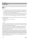
Rotation OFF

Rotation ON

1

3

2

4

6

5

7

8

9

10

12

11

Summary of Contents for Ektascan 2180

Page 1: ... SCIENCES DIVISION Eastman Kodak Company Publication No 5B9615 OCT95 Supersedes 4B4858 6 94 User s Manual for the Kodak Ektascan 2180 Laser Printer and the Kodak X Omat 180 LP or 180 LPS Processor H126_0703AA ...

Page 2: ... 1 Section 2 Printer Overview 2 1 About This Manual 2 2 General Product Overview 2 4 Printer Overview 2 7 Display Screen Overview 2 8 Keypad Overview 2 13 Control Terminal 2 16 Section 3 Basic Operations 3 1 Start Up and Shutdown 3 2 Selecting Film 3 4 Loading and Unloading Film 3 5 Using the Control Panel 3 23 Section 4 Keypad Functions 4 1 Using the Keypad 4 2 Storing Images and Printing Pages 4...

Page 3: ... for the 180 LP or 180 LPS Processor 11 6 Processor Configuration and Setpoints 11 7 Using the Access Code 11 8 Processor Setup Access Screen 11 9 Section 12 Mixing the Chemistry 12 1 Section 13 Setting Up the Processor 13 1 Processor Configuration 13 2 Selecting a Replenishment Mode 13 3 Calibrating the Replenishment System 13 10 Changing Setpoints 13 14 Standby Mode 13 18 Display Units 13 18 Sec...

Page 4: ...Crossover Procedure 16 10 Final Comments 16 11 Section 17 Kodak X Omat 180 LP or 180 LPS Sorter Kit 17 1 Introduction 17 2 General Information 17 2 Using the Control Panel 17 4 Clearing Film Jams 17 8 Sorter Error Messages Displayed on the Display Screen of the Laser Printer 17 12 Section 18 Appendix 18 1 Appendix A Setting Up Supply Magazines 18 2 Appendix B Folding the Reusable Plastic Carrier B...

Page 5: ...n explosive environment It must not be used in areas where explosive gases or vapors are present Use of controls or adjustments or performance of procedures other than those specified herein may result in hazardous radiation exposure Caution This device is intended for use only by professional trained personnel Because the imaging sections of laser printers imagers are designed differently the pri...

Page 6: ...HE LASER BEAM DANGER HIGH VOLTAGE This equipment is operated with hazardous voltage which can shock burn or cause death Remove the wall plug before servicing equipment Never pull the cord from the outlet Grasp the plug and pull to disconnect DO NOT operate equipment with a damage power cord Position the power cord so that it will not be tripped over or accidentally pulled H126_2719AC DANGER Laser ...

Page 7: ...and if not installed and used in accordance with the instruction manual may cause interference with radio communications It has been tested and found to be exempt from the limits for a Class A computing device pursuant to Part 15 Subpart J of FCC Rules which are designed to provide reasonable protection against such interference when operated in a commercial environment Operation of this equipment...

Page 8: ... Hz 120V 12A 12A 60 Hz Rochester New York 14650 EASTMAN KODAK COMPANY Made in U S A by 115V 12A 50 60 Hz 100V SUBCHAPTER J DE L ELECTR CITE SEULEMENT CODE CERTIFIE EN VERTU DU CODE CANADIAN CERTIFIED ONLY TO CANADIAN ELECTRICAL MANUFACTURED 3230 NUMBER SERIAL CODE SERVICE EKTASCAN 2180 Laser Printer KODAK 3230 3230 3230 LISTED 115B R R MGA 963877 H126_2712CC ...

Page 9: ...ISTED 3230 3230 3230 KODAK EKTASCAN 2180 Laser Printer SERVICE CODE SERIAL NUMBER 3230 MANUFACTURED CERTIFIED ONLY TO CANADIAN ELECTRICAL CODE CERTIFIE EN VERTU DU CODE CANADIAN DE L ELECTR CITE SEULEMENT SUBCHAPTER J 100V 50 60 Hz 12A 115V Made in U S A by EASTMAN KODAK COMPANY Rochester New York 14650 60 Hz 12A 12A 120V 50 Hz 60 Hz 6A 220 230 240 THIS PRODUCT COMPLIES WITH 21 CFR CHAPTER 1 ...

Page 10: ...n soil is removed wipe external surfaces dry with clean or sterile soft cloth Responsibility of the Manufacturer The manufacturer is responsible for the effects on safety reliability and performance of the Kodak Ektascan 2180 Laser Printer only if assembly operations extensions readjustments modifications or repairs are carried out by persons authorized by the manufacturer the electrical installat...

Page 11: ...Overview 5B9615 2 1 Section2 PrinterOverview Description Page Table of Contents About This Manual 2 General Product Overview 4 Printer Overview 7 Display Screen Overview 8 Keypad Overview 13 Control Terminal 16 ...

Page 12: ...D Processor Menu Flow Chart Appendix E Processor Error Messages Words that are italicized can be found in the Glossary which follows the Appendices An Index of alphabetized topics is included at the end of this manual Manual Organization This manual consists of the following sections Section 1 Safety Information provides important safety information and warnings for all users Section 2 Overview pr...

Page 13: ...using the Keypad and a flow chart of the Operator Interface Screens Sections 10 15 Kodak X Omat 180 LP or 180 LPS Processor provides Processor information Section 16 Using a 21 Step Gray Scale for Processor Quality Assurance explains procedures related to processor quality assurance Section 17 Sorter provides information on how to use the Sorter and how to clear film jams Section 18 Appendix inclu...

Page 14: ...evices The Kodak Ektascan 2180 Laser Printer is designed to be integrated with the Kodak X Omat 180 LP or 180 LPS Processor Also a Receive Magazine could be used instead of the 180 LP or 180 LPS Processor The roomlight film package allows the user to load film into two different Supply Magazines under normal room light conditions The 2180 Laser Printer and the 180 LP or 180 LPS Processor are both ...

Page 15: ... can be controlled either by the Keypad or by autofilming commands from the imaging device In Keypad Mode a Footswitch may also be used to store images In Autofilming Mode a Control Terminal or an Auxiliary Keypad may be used to access features of the Laser Printer not supported by the autofilming connection Control Terminal optional Ultrasound Keypad Footswitch data cable autofilm link CT MRI DSA...

Page 16: ...e console with autofilming or using autoprint The Laser Printer receives the image electronically to be exposed onto film in the Laser Printer If a Processor is attached the film is sent to be processed Otherwise you would select Receive Magazine for the film to be sent to a Receive Magazine and processed later Imaging Keypad Kodak Ektascan Kodak X Omat 2180 Laser Printer 180 LP Processor H126_906...

Page 17: ...rinter Overview 5B9615 2 7 Printer Overview H126_0702GA door printer latch slot cover processor switch power main built in densitometer film door keys 6 function panel control screen display H126_0702GCB ...

Page 18: ...tom half of the screen is the Command Section In the Data Section the Printer provides you with information such as the screen title the printer state and screen specific data In the Command Section you can select commands and the Printer prompts you for your next action H126_9123AC F1 F2 F3 F4 Select the desired function Start Printing Manage Study Reprinting Access Magazines Other Functions F1 F...

Page 19: ...ng the Printer is not printing films from the imaging devices but is printing test films or transporting films Offline the Printer is not accepting commands or data and is not printing films from the Print Queue The Printer is off line during power up diagnostics after certain errors and when diagnostics are run by Service Representative Turn the Printer off and on to clear the Printer and return ...

Page 20: ...de you or ask you for input for your next request Not all commands are appropriate in all situations If a command is not appropriate in a particular situation it is cleared When a command is cleared the descriptive text of the command is not visible If a cleared command becomes appropriate again the Printer displays the descriptive text line of the command again In this case the command is said to...

Page 21: ...Printer will reprint pages that were stored but not printed due to a power down situation After print jobs are recovered the prompt returns to the initial prompt as displayed When all startup diagnostics are successfully executed the Printer displays the Control Printer Screen The Printer state will be either Ready or Printing If there are any diagnostic failures the Printer will display the Error...

Page 22: ...ection 3 H126_9022GC 6 Other Functions Access Magazines Manage Study Reprinting Stop Printing Select the desired function F4 F3 F2 F1 Receive mag Ready 8 x 10C 35 x 43B 2 1 Supply Supply Processor CONTROL PRINTER screen title approximate film level prompt commands current size and Magazine Receive films in number of H126_9022GCA destination type of film in Supply Magazines in Supply Magazine s sta...

Page 23: ...filming link With an autofilming link commands are sent from the imaging device Note Some autofilming links do not accommodate all features available on the Keypad These features may be implemented by using the optional Control Terminal or the Auxiliary Keypad The operation of the Control Terminal is explained in the user information shipped with the Control Terminal The fold out Quick Reference G...

Page 24: ... located where the function is fully explained Note If a particular feature or key is not available at the time it is pressed the Invalid Key tone sounds The Keypad and complete explanations of specific key functions will be discussed in more detail in Section 4 Keypad Functions H126_2713BC QUEUE 01 READY TO STORE IMAGE ...

Page 25: ...w 5B9615 2 15 Footswitch Description The Footswitch connects directly to the back of the Keypad Pressing the Footswitch stores an image just like the Store bar on the Keypad stores an image left to right top to bottom ...

Page 26: ...be used to substitute or supplement existing autofilming or Keypad features for any device that sends commands to the Laser Printer The Control Terminal and its features will be discussed in detail in Section 5 Control Terminal H126_0021AA Control Terminal H126_0021ACA ...

Page 27: ...Start Up 2 Shutdown 3 Selecting Film 4 Loading and Unloading Film 5 Access Magazines Screen 6 Changing Film Size 8 Loading Roomlight Film in the Supply Magazine 9 Unloading Film from the Receive Magazine 16 Loading Film in the Darkroom 20 Loading Film into a Partially Empty Magazine 22 Using the Control Panel 23 ...

Page 28: ...ure the Printer displays a message that the Processor is not ready The films will remain in the Image Buffer until the Processor becomes ready You may override the message and send the film to the Processor by using the override function on the Printer Control Processor Screen See Control Processor Screen in Section 11 of Part II of this User s Manual for more information There are no films waitin...

Page 29: ... User s Guide for the Kodak Ektascan Network Interface for Laser Printer Interconnect 4 Turn off the Printer by moving the Main Power Switch to the OFF position 5 If a Processor is attached see the shutdown procedure of the Processor in Section 14 of Part II of this User s Manual When the 2180 Laser Printer is turned off or a power failure occurs system configuration and interface option informati...

Page 30: ... Note The Supply Magazines in your Printer are set up and labeled for the film sizes and types that will be used at your site If your site changes the film sizes or types that are used contact your Service Representative or see Appendix A of this manual for instructions to change the Supply Magazines setup Important You can select a film size and type even if it isn t currently in the Printer The ...

Page 31: ...Laser Printer select F3 Access Magazines from the Control Printer Screen H126_9023AC CONTROL PRINTER Processor Supply Supply 1 2 35 x 43B 8 x 10C Ready Receive mag 6 F6 F5 F4 F3 F2 F1 Other Functions Access Magazines Manage Study Reprinting Start Printing Select the desired function F4 F3 F2 F1 ...

Page 32: ...ally unlatch the Film Access Door indicate with a yellow indicator that the Supply Magazines are empty See the following illustration You may now open the Door fully and pull out one or more Magazine Drawers to remove load or unload one or more Magazines zine drawers and close door Access magazines push in maga 6 Receive mag Not Printing 8 x 10B 35 x 43C 2 1 Supply Supply ACCESS MAGAZINES H126_902...

Page 33: ...perations 5B9615 3 7 S1 S2 R 35 x 43 Clear 8 x 10 Blue Supply Magazine 1 display screen control panel function keys 6 empty magazine indicator light drawer Supply Magazine 2 drawer Receive Magazine H126_0712DA ...

Page 34: ... at the Control Terminal or Auxiliary Keypad a Press Select Film on the Keypad Note The default film size is 35 x 43 cm blue base b Press F1 to scroll through the 4 possible film sizes and 2 possible film types If a film size is available the size displays If it is not available the display will show the size and base type and not present for that film c When the desired film size displays press F...

Page 35: ...ve the Supply Magazine from the Printer in order to load roomlight film Follow these steps to load the roomlight load film in the Supply Magazine 1 Check the empty Magazine indicator lights on the front of the Supply Magazine Drawer or the display on the Control Printer Screen to determine which Supply Magazine is empty 2 Pull out the Drawer of the empty Supply Magazine and open its Lid by lifting...

Page 36: ...iscard the empty film pouch 5 Make sure you have the proper film for the Magazine 6 Place the new film package into the Magazine checking that the side labeled UP is facing up as illustrated below and that the package is fully seated in the Magazine H126_0005AA Supply Magazine H126_0005ACA ...

Page 37: ...he teeth of the Spindle at the back of the Magazine These teeth will engage to pull the film package off of the film 8 Remove tape and fold out flap 2 as numbered on the film packaging and in the illustration below H126_0006AA H126_0006ACA Supply Magazine spindle ...

Page 38: ...tton on the left hand side of the Supply Magazine lowering the Lid and pressing on the Magazine Lid until it latches on both sides Important Do not put weight on the Supply Magazine This will result in damage to the Drawer H126_0007AA release button H126_0007ACA Supply Magazine ...

Page 39: ...ch as indicated on the film packaging and in the illustration below About 1 in of the film package will hang out of the front of the Supply Magazine The package will be wrapped up by the Spindle in the Supply Magazine H126_0010AA Supply Magazine H126_0010ACA ...

Page 40: ...rom the Supply Magazine Drawer return it to the appropriate Supply Magazine Drawer in the Laser Printer 12 Push the Supply Magazine Drawer all the way in until it latches and close the Film Door of the Printer H126_0717GA drawer Magazine Supply film door H126_0717GCA ...

Page 41: ... within a preset time delay the Printer will automatically start printing Note The time delay 1 60 seconds is configured at installation A motor will remove the package from the film The Printer will become Ready and the Display Screen will indicate that the Supply Magazine is full of film H126_9025AC CONTROL PRINTER Processor Supply Supply 1 2 35 x 43B 8 x 10C Not Printing Receive mag 0 F6 F5 F4 ...

Page 42: ...hoes or nylon materials 1 Select F3 Access Magazines from the Control Printer Screen The Printer will automatically unlatch the Film Access Door 2 Open the door fully and pull the Receive Magazine Drawer all the way out Manage Study Reprinting H126_9026AC CONTROL PRINTER Receive mag Supply Supply 1 2 35 x 43B 8 x 10C Ready Receive mag 50 F6 F5 F4 F3 F2 F1 Other Functions Access Magazines Stop Prin...

Page 43: ... Magazine to zero Important If the film is not removed from the Receive Magazine after removing the Magazine from the Printer a film jam may occur when the Magazine becomes full The Receive Magazine can hold 50 films 3 Take the Receive Magazine to the darkroom Caution Unload the darkroom film in total darkness No darkroom lights or safe lights can be used 4 Turn off all darkroom lights and safelig...

Page 44: ...he films by the edges only Flip the film over so that it is emulsion side up 7 Process the film with the emulsion side up 8 Turn on darkroom safelights and lights 9 Close the Magazine Lid and press in on the 2 Side Latches until they snap into place 10 Return the Receive Magazine to the Receive Magazine Drawer push the Drawer all the way in and close the Film Door H126_0012AA Receive Magazine H126...

Page 45: ...odak X Omat 180 LP or 180 LPS Processor If none of the options is selected within a preset time delay the Printer will automatically start printing Note The time delay 1 60 seconds is configured at installation H126_9124AC F1 F2 F3 F4 Select the desired function Start Printing Access Magazines Other Functions F1 F2 F3 F4 F5 F6 0 Receive mag Not Printing 8 x 10C 35 x 43B 2 1 Supply Supply Receive m...

Page 46: ...or the Magazine Note Smaller films may not be loaded into Magazines that are configured for larger films 2 Place the Magazine and the film package on a clean work table Position the Supply Magazine so that the Handle is to your left 3 Open the Magazine Lid by lifting the Cover Release Latches on the two front corners of the Supply Magazine 4 Remove the Plastic Carrier Board from the Magazine and p...

Page 47: ...he film package and with the notch in the front right hand corner or the rear left hand corner put the stack of film inside the Plastic Carrier Board as illustrated in the side view below H126_3700AC film plastic carrier board H126_3700ACA ...

Page 48: ...he Magazine Lid until it latches on both sides 9 Return any unused film to its light tight container and turn on the darkroom safelights Loading Film into a Partially Empty Magazine When loading film into a partially empty Magazine 1 Make sure to turn off all room lights before opening the Magazine Lid 2 Place the new film under the old film to rotate the film in the Magazine H126_0009AA notch fil...

Page 49: ...after the Printer completes its startup procedure The following screen displays on the Display Screen most of the time during normal operation This screen shows the Processor as the selected destination Also the Receive Magazine could be selected as the destination Printing images is discussed in detail in Section 4 Keypad Functions H126_9028AC Film in Proc CONTROL PRINTER Processor Supply Supply ...

Page 50: ...lease wait Then the Printer enables the other commands and changes the printer state to either Printing or Ready When the Stop Printing function is invoked the Printer toggles the command and changes the state to Not printing Manage Study Reprinting H126_9029AC CONTROL PRINTER Processor Supply Supply 1 2 35 x 43B 8 x 10C Ready Receive mag 6 F6 F5 F4 F3 F2 F1 Other Functions Access Magazines Start ...

Page 51: ...n Section 7 Study Reprinting It is accessed when you select F2 on the Control Printer Screen H126_9110AC 9 5 3 6 2 MR2 MR1 CT3 STUDIES Manage Selected Source Manage All Sources CT2 CT1 SOURCE Manage All Sources Select Source and Manage or F4 F3 Printing MANAGE STUDY REPRINTING 42 Studies F2 F1 F6 Return ...

Page 52: ...ient identification number date and time of the study source name status protected or unprotected and scroll bar position within the list of studies are displayed 00012345678 00012345689 H126_9111AC PROT CT3 UNPROT CT3 10 Jan 95 8 02 10 32 Reprint Study Unprotect Study 10 Jan 95 change study Protection Select a study and Reprint or F4 F3 Printing MANAGE STUDIES 5 Studies F5 F2 F1 F6 Unprotect All ...

Page 53: ...n Select F3 to access this display This screen stops the printing of films and opens the Film Door so that you can fill the Supply Magazines or remove the Receive Magazine Note You may continue to store images and they will be held in the buffer ACCESS MAGAZINES Supply Supply 1 2 35 x 35B 11 x 14C Not Printing Receive mag zine drawers and close door 41 Access magazines push in maga H126_9031AC ...

Page 54: ...inter stops printing and prompts you to turn the Printer Door Latch You must open the Printer Door within 5 seconds of the prompt After you open the Printer Door the Printer changes the prompt to Access printer interior push door closed and turn latch To close the Printer Door push it closed and turn the Latch clockwise to the vertical position OTHER FUNCTIONS Ready F1 F2 F3 F4 Select the desired ...

Page 55: ...splay the Select Destination Screen This option does not appear if the Processor was not installed at system configuration time Press F3 to increase the number of films in a range of 1 to 99 and ALL The key may be held down in autorepeat mode ALL will transport all films from the selected Supply Magazine Press F4 to decrease the number of films in a range of 1 to 99 and ALL The key may be held dow...

Page 56: ...ussed in detail in the Processor section which is in Part II of this User s Manual Show More Functions The F5 function displays additional options as shown in the screen illustration on page 3 31 OTHER FUNCTIONS Ready F1 F2 F3 F4 Select the desired function Calibrate Printer Access Film Path Transport Films Control Processor Return Show More Functions F6 F5 15 Oct 95 09 26 H126_9032AC ...

Page 57: ...ontrol Printer Screen the screen which you used to get to the Other Functions Screen OTHER FUNCTIONS Ready F1 F2 F3 F4 Select the desired function Manage Print Queue Show Printer Info Read Reference Strip Print Test Films Return Show More Functions F6 F5 15 Oct 95 09 26 H126_9034AC ...

Page 58: ... the jobs in the print queue and allow you to delete jobs H126_9038AC F4 Delete All Jobs Queued Queued Norm Norm Norm 4 6 5 3 2 4 3 5 3 2 Queued In prog In prog STAT Norm MR2 CTRM2 US MR1 CTRM1 STATUS PRIO FLM PG SOURCE 9job 42flm Return Delete Selected Job Select the desired function F6 F3 F2 F1 Printing PRINT QUEUE ...

Page 59: ...int jobs flm Total number of films in the print queue Each job is a copy of a study in the print queue Source a 5 character name for the imaging device If a name is not assigned to a imaging device the Printer will display Also the source can be Test for any test or transport films printed PG Number of pages in the job FLM Number of films remaining to be printed for the job Prio Priority either No...

Page 60: ...print because the Printer Magazine does not have the required film type the required film type displays such as 35x43B The queue display is updated as new jobs are added to the print queue and printed jobs are removed from it If the print queue is empty only the Return option displays Press F1 to select the previous job the job that immediately proceeds the job that is currently selected Press F2 ...

Page 61: ...e Print Queue Screen as described in the previous section H126_9038AC F4 Delete All Jobs Queued Queued Norm Norm Norm 4 6 5 3 2 4 3 5 3 2 Queued In prog In prog STAT Norm MR2 CTRM2 US MR1 CTRM1 STATUS PRIO FLM PG SOURCE 9job 42flm Return Delete Selected Job Select the desired function F6 F3 F2 F1 Printing PRINT QUEUE ...

Page 62: ...nfirm that you really want the job deleted or given a chance to back out without deleting the job Press F1 to delete the selected job and return to the Print Queue Screen Press F6 to return to the Print Queue Screen H126_9039AC Queued Queued Norm Norm Norm 2 2 1 2 1 4 3 5 3 2 Queued In prog In prog STAT Norm MR2 CTRM2 US MR1 CTRM1 STATUS PRIO FLM PG SOURCE 9job 42flms No Yes quit Select Yes to del...

Page 63: ... of the error message Press F2 to display the Show Versions Screen The versions of Printer software components display At the Show Versions Screen press F1 to display the Show Interfaces Screen The Printer displays the status of the interfaces that have established communication with the Printer at the time this screen displays For each interface the Printer displays Node Id Type Version and Sourc...

Page 64: ...en information will scroll to the left to show the previously displayed information At the Show Actuations by Source Screen press F2 to display the next sources The screen information will scroll to the right to show the next information Note For the Show Previous and Show Next functions the screen scrolls left to right and right to left to display the information rather than up and down Read Refe...

Page 65: ...een will change to either the Receive Magazine or the docked Processor Press F3 or F4 to move forward or backward through to choices of Calibration Cal Results Flat Field and SMPTE test films Press F5 to print the selected test film Press F6 to return to the Other Functions Menu PRINT TEST FILMS Ready F1 F2 F3 F4 Make selections and Print Change Supply Magazine Change Destination Previous Test Fil...

Page 66: ...o get to the Other Functions Screen Show More Functions The F5 function displays the additional options in the Other Functions Screen Select Destination Assign Processor Sorter Bins H126_9037AC 15 Oct 95 09 26 F5 F6 Show More Functions Return Set Time and Date Select the desired function F4 F3 F2 F1 Ready OTHER FUNCTIONS ...

Page 67: ... Press F1 and F2 to move the black highlighted box to the day month or year or the hour or minutes that you want to change Press F3 to increase and F4 to decrease the date or time value Press F5 to update the time or date to the new values SET TIME AND DATE F1 F2 Return F6 1 Oct 95 15 36 F3 F4 F5 Increase Decrease Set to New Values Select the desired field s and modify when done Set Ready H126_909...

Page 68: ...n be used You will use the Select Destination Screen when you set up your Printer and when changing from the docked Processor to the Receive Magazine to print or changing back to the Processor This feature tells the Printer whether your exposed films should go to a docked Processor or a Receive Magazine If you add a Processor to your Printer at a later date you will use this screen to change the d...

Page 69: ...nsecutively until the last site At that point the first site is selected and the cycle continues Press F3 to select the site below the currently selected site If you continue to press F3 the sites are selected consecutively until the last site At that point the first site is selected and the cycle continues Press F6 to return to the previous screen the screen which you used to get to the Select De...

Page 70: ...User s Manual 3 44 5B9615 ...

Page 71: ...ting Pages 10 Autoprint Printing 10 STAT Printing 10 Deleting Images or Pages 11 Deleting Images 11 Deleting Pages 11 Deleting Studies 11 Program Options 12 Tone Scaling 13 Entering and Leaving the Program Function 14 Window Options 15 Window Width 15 Window Level 16 Curve Shape 17 Curve Series 18 Print Options 20 Contrast Option 22 Image Dmin Image Dmax and Border Dmax 22 Contrast 23 Configuratio...

Page 72: ...sheets of one kind of film Area Function Top line left side System status for example Ready to Store Image Top line right side Number of pages remaining in the queue for the associated imaging device Other imaging devices will have their own queues that will be displayed on their keypads Bottom line left side Displays information about such items as deleted images Bottom line right side Displays u...

Page 73: ... is closed This feature ensures that the pages of the study will be properly collated Copies The Copies display and the or arrow keys below it are used to change the number of copies requested for a page or a study of images Copies must be set before requesting a print Format The Format display and the or arrow keys below it are used to scroll through the format options to change the format for a ...

Page 74: ... are printed in order and not intermixed The study feature can be turned on or off Function Keys F1 through F4 Used primarily in Program mode The system will prompt you for necessary input Select printer This feature is available for Printers interconnected through the network For information regarding the operation of interconnected Laser Printers please refer to the User s Guide for the Kodak Ek...

Page 75: ...es storing images and printing pages using a Keypad If autofilming is used or these functions are controlled by the imaging device check the appropriate imaging device manual for the correct procedures Most formats activate the Position Store keys on the Keypad H126_2713BC QUEUE 01 READY TO STORE IMAGE ...

Page 76: ...ed below The options are changed through the Keypad The Kodak Ektascan 2180 Laser Printer retains the most recently used format for the next page Sixteen standard formats are available They are formats 1 2 4 6 8 9 12 15 16 20 24 30 35 and Kodak formats F1 F2 and F3 The formats that are available depend upon the amount of image memory that is installed in the Laser Printer the input image size the ...

Page 77: ...s in this group may be selected to store or delete the image for this position Solid red LEDs illuminate in all four positions when the position is filled Locate group B in the figure below These six keys represent six separate image store positions Each key is used to store or delete an image in its assigned position A solid red LED illuminates the position chosen A B Special Format F1 the size o...

Page 78: ...in a group may be selected to store or delete the image for these positions Solid red LEDs illuminate in all four positions when the position is filled Locate group C in the figure below These nine keys represent nine separate image store positions Each key is used to store or delete an image in its assigned position A solid red LED illuminates the position chosen a 15 up the size of a 6 up the si...

Page 79: ...mal or reverse blackbone tone scale for each image The default tone scale is normal Note When the tone scale is reversed the REVERSE indicator light is lit on the Keypad To change the tone scale from its current state press Reverse on the Keypad Number of Copies The maximum number of copies that you can select is 99 If operating in Page Mode the number of copies must be changed prior to printing I...

Page 80: ... allows you to move a page or study ahead of all non STAT pages in the print queue Any STAT job whether it be a page or a study moves ahead of any normal job but behind an earlier STAT job in the print queue To print a STAT page 1 Press Stat before issuing the Print command or if Autoprint is enabled before storing the last image on the page When you press Stat the green indicator light is illumin...

Page 81: ... was stored This method of deleting an image is available when the position store keys are illuminated Deleting Pages If operating in Page Mode press Delete Mode and then select Delete Page to delete a partial or complete page Note A page must be deleted before it has been placed in the print queue Deleting Studies When in Study Mode press Delete Mode and then Press F1 to delete the page that is c...

Page 82: ... allows access to the functions which do not have dedicated keys on the Keypad Included in the functions of this key are the following items Window Options Print Options Reprint Options Configuration There are sub options under the above headings Such options include Curve Shape Interpolation Contrast Autoprint Audio and Rotation Definitions of these terms can be found in the Glossary ...

Page 83: ...e has been properly adjusted This monitor adjustment should not be changed once the tone scaling has been completed To adjust the tone scale use the following procedure 1 Calibrate the Laser Printer 2 For each remote Keypad to a Laser Printer Adjust the minimum to maximum density Image Dmin Image Dmax and Border Dmax Use the Keypad Program key to enter the values Adjust the curve shape Use the Key...

Page 84: ...isplayed and the numeric keypad will be active at this time To exit the Program Function press Program If a parameter has been changed and is valid it is saved Note F3 REPRINT OPTIONS is discussed in Section 7 Study Reprinting F1 WINDOW OPTIONS F2 PRINT OPTIONS F3 REPRINT OPTIONS F4 CONFIGURATION H126_2717BC QUEUE 01 READY TO STORE IMAGE ...

Page 85: ...onitor do not change them Window Width To change the window width press Program F1 F1 The system will ask you to enter a window width value Note The valid window width value range is between 1 and 4096 The default value is 256 Change the window width to 4096 when connecting to a 12 bit digital output workstation or imaging device Note Enter a value on the numeric section of the Keypad and to remai...

Page 86: ...id window level value range is between 0 and 4095 The default value is 128 Change the window level to 2048 when connecting to a 12 bit digital output workstation or imaging device Enter the value and to remain in the Program Mode press E on the numeric keypad To specify the value and exit from the Program Mode press Program WINDOW LEVEL ENTRY WIDTH 128 ...

Page 87: ...lt value is 3 In some cases the curve shape may be changed if images have already been stored on a page In other cases the curve shape may be changed only when the page is empty It depends on how the Printer was configured for your site Enter the value and to remain in the Program Mode press E on the numeric keypad To specify the value and exit from the Program Mode press Program CURVE SHAPE ENTRY...

Page 88: ... within the Program option To use the Curve Series option 1 Display a desired image on the monitor and do not change the image during this procedure 2 Press Program F1 F4 3 Wait for the Laser Printer to do the following a store the image 6 times using 6 curve shapes b send the page to print 4 Process that page of images 5 Use the illustrations on the next page to select the curve shape number of t...

Page 89: ...Keypad Functions 5B9615 4 19 Figure 4 1 Curve Shapes 0 through 5 on 35 x 43 cm 35 x 35 cm and 11 x 14 in film H027_0054AA ...

Page 90: ...mages to their maximum size based on the selected format The No Magnification option prints images without enlarging them The default is Cubic Spline 1 To change the interpolation type press Program F2 F1 The current interpolation type will be displayed and the system will prompt you to press F1 to display the next interpolation type When the desired interpolation type is displayed press E on the ...

Page 91: ...ype press Program F2 F2 The current Border state will be displayed as BLACK or CLEAR To change the Border press F1 followed by E on the numeric keypad or Program Trim Option The Trim Option allows a 2 pixel wide frame around each image To change the trim option from its current state press Program F2 F2 The current state will be displayed as TRIM ON or TRIM OFF To change it press F1 followed by E ...

Page 92: ...k border the trim is white You should understand the relationship between image density restriction and contrast adjustment If you reduce both Image Dmax restrict and contrast negative contrast the density will be reduced more than you might expect The 2180 Laser Printer allows each imaging device to select Image Dmin Image Dmax and Border Dmax individually For example an ultrasound user might sel...

Page 93: ...5 The means higher contrast and the means lower contrast The default value is 0 When entering a negative value press the minus sign first Enter the value and to remain in the Program Mode press E on the numeric keypad To specify the value and exit from the Program Mode press Program To enter the Reprint Options Menu press Program F3 Note See Section 7 Study Reprinting CONTRAST ENTRY CONTRAST 0 ...

Page 94: ...s you to specify that a page should be sent to the print queue automatically when the page format has been filled with images When autoprint is not enabled press Print on the Keypad to send each page to the print queue The default setting for autoprint is ON To change the autoprint status press Program F4 F1 The current setting will be displayed To change the autoprint setting press F1 E Note The ...

Page 95: ...To change the audio status press Program F4 F2 The current setting will be displayed To change the current setting follow the system prompts and press E on the numeric keypad Study Option The Study Option allows you to work in either Page Mode or Study Mode Study Mode groups several pages of images together Pressing Study signals the end of a study A study allows you to print pages 1 2 3 from imag...

Page 96: ... rotation setting press Program F4 F4 To change the current setting press F1 The setting will toggle between OFF and ON To store the new setting press E on the numeric keypad To store the new setting and exit from the Program Mode press Program The following is an example of a 12 up format The diagram at the left indicates the arrangement of the images on the film with rotation OFF The diagram at ...

Page 97: ...Keypad Functions 5B9615 4 27 common text common text 1 2 3 4 5 6 7 8 9 10 11 12 Rotation OFF Rotation ON 1 3 2 4 6 5 7 8 9 10 12 11 ...

Page 98: ...pear on the keypad display If the F2 key is not pressed the autofilming link controls the Laser Printer The Keypad acts only as a display The Keypad will display printer messages error messages for the Interface queue status film supply quantity the image store positions The image store positions map will show the current page layout or where the images have been stored within this layout The map ...

Page 99: ...ity depends on the imaging device Delete Image availability depends on the imaging device Study Not Available Stat Reverse Copies Format availability depends on the imaging device Program Select Printer F3 Select Film F4 Footswitch support Note If a particular feature is not available the unit will sound a tone when you try to access the feature Note Pressing F2 again will return you to the Displa...

Page 100: ...User s Manual 4 30 5B9615 ...

Page 101: ...otation 9 Interpolation Type 9 Select Film 9 Polarity 9 Store Position 10 Print a Page 10 Delete Defined 10 Delete a Position 10 Delete a Page 10 Page Function and Parameter Function 10 Image Setup 11 Common Text 12 Update Text 13 Deleting Text 13 Change Destination 14 Troubleshooting the Control Terminal 14 Blank Display Screen 14 Garbled Screen 14 Locked Screen 15 Vertical Misalignment of Displa...

Page 102: ...er These features include Dmin and Dmax settings contrast adjustment and common text Note Occasionally an autofilming device will override a desired function that has been set up with the Control Terminal If this happens contact your Service Representative regarding the operation of the imaging device with the Laser Printer H126_0021AA Control Terminal H126_0021ACA ...

Page 103: ...of Copies Set Print Priority Set Rotation Enter Interpolation Type Select Film size and base Set Polarity Set Page Functions Return Image Setup Enter Widow Width Enter Window Level Set Border Density Set Trim Enter Contrast Enter Image Dmin Enter Image Dmax Enter Border Dmax Change Key Curve Shape Curve Series Return Common Text Setup Update Text Delete Text Return ...

Page 104: ...e for the Kodak Ektascan Network Interface for Laser Printer Interconnect Caution Never press Set Up at the top right of the Control Terminal keyboard This key is used to reconfigure the Terminal Pressing it will invalidate the customized installation default settings for the Control Terminal If Set Up is accidentally pressed and a menu is displayed press Set Up again to exit from that menu ...

Page 105: ...l and item 1 is accidentally selected the Mode Selection Menu will be displayed At that menu press Esc to return to the Terminal Type Menu and select item 2 If the user indicates a WYSE terminal specification when it is not a WYSE terminal and makes a selection from the Mode Selection Menu with the non WYSE terminal the Control Terminal display may show a garbled message If the user presses Esc an...

Page 106: ... device is to be affected by the Control Terminal operation Note The imaging device names shown on the Input Selection Menu are user specified TERMINAL TYPE MENU 1 Kodak Control Terminal WYSE 2 Kodak Service Engineering Terminal Enter Menu Item 1 MODE SELECTION MENU 1 Laser Printer Operations 2 Service Operations Enter Menu Item 1 INPUT SELECTION MENU 1 First imaging device 2 Second imaging device...

Page 107: ...ns as listed After the system is configured item number 5 Change Control Link is dropped and 6 options remain When an option from the Main Menu is selected press Enter The next screen shows both the submenu options and at the bottom of the screen a list of the Function keys F1 through F10 and what they do Where more options exist than can be shown on one list the F9 key will be designated as the C...

Page 108: ...functions will be displayed on the screen in an area that is labeled Current Settings F1 Change Format F2 Number of Copies F3 Print Priority F4 Rotation F5 Interpolation Type F6 Select Film F7 Polarity F9 Page Function F1 Store Defined F2 Store Position F3 Print Page F4 Delete Defined F5 Delete Position F6 Delete Page F9 Param Func F10 Return ...

Page 109: ...nter the number of copies 1 99 Print Priority This function allows the user to either specify that pages or studies be printed as STAT and move ahead of other non STAT pages or studies in the printer queue remove the STAT condition The STAT key toggles the current setting ON or OFF Rotation All images to be rotated 90 when printed on film Interpolation Type The Current Settings area of the menu sc...

Page 110: ...ect the positions that have a stored image Print a Page Prints the page displayed Delete Defined Defined images will be deleted first from the last stored position and then the reverse of the default store sequence That is they are deleted from bottom to top and from right to left Delete a Position Enter the number value that corresponds to the desired delete position Delete a Page Deletes the cur...

Page 111: ...vel F3 Border F4 Trim F5 Contrast F6 Image Dmin F7 Image Dmax F9 Change Key F1 Curve Shape F2 Curve Series F9 Change Key F10 Return If an option is selected that is not available on this Laser Printer the Control Terminal will sound an Invalid Key response Note Refer to Program Options on page 4 12 to obtain details of the features listed above ...

Page 112: ...f the film The text can contain the date that the film was printed the time that the film was printed the film count within the study For example 01 06 indicates the 1st of 6 films any other text desired For example the hospital name and the imaging device could be placed at the bottom of the film When this item is selected the screen displays the current text specification of the imaging device a...

Page 113: ... and time To print the print date time and or page number for total pages in the study type the following macros in the text Finally the system asks you to specify B for black text or C for clear text and S ave R evise or Esc to quit Deleting Text If F2 is selected the system asks for a verification before the text is deleted Macro Printed As Example STORDAT dd MMM yy 29 OCT 92 STM hh mm 15 01 STO...

Page 114: ...icating successfully with the Laser Printer This will indicate whether or not the interface is responding 5 If none of the above steps refresh the screen contact your Service Representative Garbled Screen If the user indicates a WYSE terminal specification when it is not a WYSE terminal and makes a selection from the Mode Selection Menu with the non WYSE terminal the Control Terminal display may s...

Page 115: ...erminal characteristics were changed To re establish the WYSE terminal as a Control Terminal 1 Press the Set Up key 2 Press F2 3 Use the Space Bar until WYSE 50 is displayed in the upper left corner 4 Press the Set Up key 5 Press the Space Bar until Yes is displayed 6 Press the Set Up key 7 The next menu item selected will re align the Display Screen Error Codes If a fatal interface error occurs a...

Page 116: ...User s Manual 5 16 5B9615 ...

Page 117: ...ption Page Table of Contents Overview 2 General Information 2 When to Calibrate 4 Calibrating the 2180 Laser Printer 5 Using a Stored Calibration Table 5 Performing the Calibration 5 Calibrate Printer Screen 6 Calibration Data Entry Screen 9 Checking Calibration 10 Calibration Results Film 10 ...

Page 118: ... place while the Laser Printer is printing the new calibration takes effect only when all copies of the current page have finished printing It is important to understand the difference between calibrating the Printer and calibrating the Densitometer Calibration of the Densitometer will be discussed in Maintaining the Densitometer in Section 8 You should also understand the difference between the C...

Page 119: ...r 5B9615 6 3 Rochester NY General CT1 12 03 06 15 May 92 1 2 3 4 5 6 7 8 9 9 8 7 6 5 4 3 2 1 NOT FOR CALIBRATION Rochester NY General CT1 12 03 06 15 May 92 USE FOR CALIBRATION H126_2721CC calibration test film calibration results film ...

Page 120: ...her the emulsion number has changed read the label on the side of the box of film Kodak Diagnostic Film EHFL Ektascan 100 CAT 828 1578 10 TM FAST LOAD PACKAGE 100 SHT X cm Emul No Exp 555 666 77 CC 10 1994 10 1994 828 1578 555 666 77 CC CAT 456777 R012 HNFL EHFL 10 35 X 43 cm CAT 828 1578 CAT 828 1578 CAT 828 1578 10 1994 555 666 77 CC 10 1994 10 1994 555 666 77 CC 555 666 77 CC HNFL EHFL 10 100 1...

Page 121: ...table Performing the Calibration 1 Check that the Printer and the Processor if one is attached is warmed up 2 Access the Other Functions Screen 3 Press F1 from the Other Functions Screen to access the Calibrate Printer Screen OTHER FUNCTIONS Ready F1 F2 F3 F4 Calibrate Printer Access Film Path Transport Films Control Processor Return Show More Functions F6 F5 15 Oct 95 09 26 F6 F5 F4 F3 F2 F1 Sele...

Page 122: ...e film type field will change to reflect the new film type F1 will be cleared if there is only 1 film type Press F2 to change the destination 2 Press F3 to print the Calibration Test Film CALIBRATE PRINTER Printing F1 F2 F3 F4 Film Read Film or Enter Data Change Film Type Change Destination Print Calibration Film Read Calibration Film Return Enter Density Data F6 F5 Film type 35 x 43B To Receive m...

Page 123: ...tion 4 Do either step 5 or step 6 to enter the density data into the Printer In step 5 the density data is read by the built in Densitometer and entered into the software of the Printer Do step 6 if you measure the density values at an off line Densitometer and then enter them at the Control Panel Note Do not place the Calibration Test Film in the slot of the Densitometer until prompted to do so H...

Page 124: ...splays the message Calibration in progress please wait If the calibration is successful the Printer changes the prompt to Printer calibration successful If any errors occur during calibration the Printer will display the Error Recovery Screen The existing calibration table is not affected Printed Errors and the Error Recovery Screen will be discussed in detail in Section 8 Troubleshooting and Erro...

Page 125: ...ty step Press F3 to increase the selected value in the range of 0 00 to 3 99 The key may be held down in autorepeat mode Press F4 to decrease the selected value in the range of 0 00 to 3 99 Repeat this process as many times as is necessary and then continue to step 2 2 Press F5 to compute calibration If calibration is not successful the Error Recovery Screen will be displayed If the calibration is...

Page 126: ...creen Calibration Results Film You may verify that the calibration was successful by checking the density of steps 1 9 They should be in equal increments Important Do not use the Calibration Results Film to calibrate the Printer calibration results film H126_2723AC 1 2 3 4 5 6 7 8 9 NOT FOR CALIBRATION General CT1 12 03 06 15 May 92 Rochester NY ...

Page 127: ...dy Reprinting From the Main Control Panel 4 Manage Study Reprinting 4 Reprint Study 7 Protected or Unprotected Studies 8 Keypad 10 Overview 10 Storing Studies at the Keypad 10 Reprint Options 12 Study Options 12 Sorting Options 13 Selecting and Reprinting Images 14 Reprinting a Study Using Date 14 Reprinting a Study Using Study 15 ...

Page 128: ...e it is known as a job however after the job is printed the study remains on disk until it is deleted Protected vs Unprotected Studies Studies may be protected or unprotected see Protected and Unprotected Studies page 7 8 Protected studies remain on the system until they are manually deleted To prevent a study from being deleted protect the study Unprotected studies remain on the system as long as...

Page 129: ...le source has been selected only the studies from that source will be available Keypad If you have the Keypad Option installed you may select a study based on a single source or all sources date and time or study number depending on the study and sorting options that have been set up in advance or that you specify from the keypad at the time the study is reprinted ...

Page 130: ...nt study for reprinting from the Main Control Panel Select F2 to access Manage Study Reprinting H126_9122AC F1 F2 F3 F4 Select the desired function Start Printing Manage Study Reprinting Access Magazines Other Functions F1 F2 F3 F4 F5 F6 6 Receive mag Ready 8 x 10C 35 x 43B 2 1 Supply Supply Processor CONTROL PRINTER ...

Page 131: ...4 if you want to print studies from one source or all sources The Printer displays the total number of studies selected from the Manage Study Reprinting screen The Printer displays Date and time that the study was stored Source name as displayed in the Manage Study Reprinting screen Protected PROT or Unprotected UNPROT status A scroll bar that shows the position of the displayed studies relative t...

Page 132: ...s the scroll bar and all commands except Return are cleared 00012345678 00012345689 H126_9111AC PROT CT3 UNPROT CT3 10 Jan 95 8 02 10 32 Reprint Study Unprotect Study 10 Jan 95 change study Protection Select a study and Reprint or F4 F3 Printing MANAGE STUDIES 5 Studies F5 F2 F1 F6 Unprotect All Studies Return ...

Page 133: ... Select F1 or F2 to change the copy count Priority status toggles between NORM for normal priority or STAT for emergency priority Select F3 to change the priority Select F4 to place the study in the queue for reprinting Select F5 to display the next study in the list If there are no more studies this command is cleared 00012345689 H126_9112AC Increase Copy Count Decrease Copy Count PROT CT3 1 Norm...

Page 134: ...d when necessary to make space for new studies to be stored Note Protecting studies reduces the number of new studies that can be stored 00012345678 00012345689 H126_9111AC PROT CT3 UNPROT CT3 10 Jan 95 8 02 10 32 Reprint Study Unprotect Study 10 Jan 95 change study Protection Select a study and Reprint or F4 F3 Printing MANAGE STUDIES 5 Studies F5 F2 F1 F6 Unprotect All Studies Return ...

Page 135: ...ted from the Manage Studies screen the Unprotected Study Confirm screen is accessed to confirm your selection 00012345678 00012345689 H126_9113AC Unprotect the selected study No F6 5 Studies UNPROTECT STUDY CONFIRM Printing F1 Select Yes to confirm No to quit 10 Jan 95 Yes 10 32 8 02 10 Jan 95 CT3 UNPROT CT3 PROT ...

Page 136: ...can reference studies for printing If you select the Page Mode of operation each page will be referenced as a study If the Study Reprint feature is used often it is recommended that the Study Mode versus the Page Mode be selected at the Keypad to reduce the number of studies needing to be referenced Storing Studies at the Keypad Optionally if Keypad Study Reprinting is installed studies may be ide...

Page 137: ...the study number after each page If the Keypad is in Study Mode each page of the study will have the same number With the Keypad Option installed in addition to date and time and source you will have the added convenience of reprinting studies based on the study number Additionally you will be able to change the order of the display so that either date and time or study number displays at the top ...

Page 138: ...ies For CT3 or any other source With this setting selected only the pages or studies from the selected device can be recalled at the keypad for reprinting You may change the source selection at any time Note The use of CT3 is only for example Your imaging device name will display By pressing F1 again the screen changes to the one below Press Enter to accept this setting or press F1 to select Manag...

Page 139: ...e Enter Study Number screen press Program F3 Reprint Options F2 Sorting Options F4 The current setting displays See the screen below which displays the Sorting Option Sort by Study 2 To accept the displayed option Press Enter or press F1 to select the other setting in this case Sort By Date Time When you choose Sort by Study all of the studies in the data base are sorted and available for display ...

Page 140: ...g steps 1 From either of the screens shown above press F1 The following screen displays 2 Press F2 to select a previous study for reprinting The following screen displays 3 Press F2 to select the study by date and time The screen below displays 4 Press F2 to display the Date Entry screen 5 On the Date Entry screen type the date of the study you want retrieved for reprinting ENTER STUDY NUMBER ENTE...

Page 141: ...plays on the screen Because you selected Date Time the date and time displays first with the study number following it as shown in the example below From this screen you may scroll backward F1 or forward F2 to find the exact study you want to reprint or you may press F3 to protect the study see Protected or Unprotected Studies page 7 8 9 When the correct study number displays on the screen press P...

Page 142: ...e screen Because you selected Study the study number displays first with the date and time following it as shown in the example below From this screen you may scroll backward F1 or forward F2 to find the exact study you want to reprint or you may press F3 to protect the study see Protected or Unprotected Studies page 7 8 14 When the correct study number displays on the screen press Print to print ...

Page 143: ...rt 3 Film Transport with a Kodak X Omat 180 LP or 180 LPS Processor 4 Film Transport with Receive Magazine 5 Film Jams 6 Error Messages 11 General Information 11 Show Error Log Screen 11 Error Recovery 13 Error Recovery Screen 14 Preventive Maintenance 15 Cleaning and Sterilization 15 Maintaining the Densitometer 16 How to Contact Service Personnel 19 ...

Page 144: ...he Film Door of the Printer Before opening the Film Door read the Safety Information that is provided at the beginning of this manual and note the location of the laser beam in the Printer Warning DANGER AVOID LASER BEAM THIS EQUIPMENT USES A VISIBLE RED LASER LASER RADIATION CAN BE PRESENT WHEN THE MACHINE IS OPERATED WITH THE PANELS OFF AND THE INTERLOCKS DEFEATED AVOID DIRECT EXPOSURE TO THE LA...

Page 145: ...om the Other Functions Screen to move film through the Printer and Processor without printing on the film This may be used for processing a pre exposed sensitometric film to clear out fogged films from the Supply Magazine or to move preprinted films to the Processor The Transport Films Screen is discussed in Section 3 ...

Page 146: ...m is squared on the Registration Table and pushed to the left The Slow Scan Assembly moves the film smoothly and holds it in focus while the film is being exposed by a laser The laser is located in the Fast Scan Assembly Next the piece of unprocessed film goes down a chute in the Exposed Film Path Assembly and onto the Receive Magazine or exits the Laser Printer through the Processor Docking Assem...

Page 147: ...ting and Error Messages 5B9615 8 5 Film Transport with Receive Magazine This view shows the film path without a docked 180 LP or 180 LPS Processor The exposed film goes to an internal Receive Magazine H126_0707GA ...

Page 148: ...curs the Display Screen of the Control Panel will display a message to tell you where to look Inside the Film Door is a label which suggests where to look for film jams 1 3 2 H126_0723GA picker assembly chute assembly registration assembly H126_0723GCA ...

Page 149: ...s 5B9615 8 7 Film jams may occur in the following places the Picker Assembly the Registration Assembly the Chute Assembly The illustrations on the following pages identify each of these areas 1 H126_0724GA picker assembly H126_0724GCA ...

Page 150: ... film must be destroyed 4 Check the Receive Magazine If film is partly in the Receive Magazine close the Printer door and press Start Printing to automatically pull the film into the Receive Magazine 5 Carefully lower the Picker Assembly Lift the cover of the Picker and remove the film 6 Check the Registration Assembly for film jams If film is in the Rollers pull it out ...

Page 151: ...Troubleshooting and Error Messages 5B9615 8 9 2 H126_0725CA Supply Magazines registration assembly H126_0725CCA ...

Page 152: ...ull it out Caution If film has gone partly into the Processor open the lid of the Processor and pull the film out through the Processor and not back through the Printer If the wet film is pulled back through the Printer the chemicals will cause damage to the Printer parts 3 H126_0726GA assembly diverter door chute assembly chute H126_0726GCA ...

Page 153: ...t is located on the Laser Printer Show Error Log Screen Press F1 from Show Printer Info Screen to display the Show Error Log Screen SHOW PRINTER INFO Printing F1 F2 F6 Select the desired function Show Error Log Show Versions Return Service 1 800 3KODAK3 Serial no 123456 K no 123 4567 Actuations 1995 1994 Total 59917 33472 26445 Aug 95 Jul 95 4186 3901 Show Actuations by Source F3 H126_9035AC ...

Page 154: ... of error messages Press F1 to display the previous earlier message Press F2 to display the next later message Press F6 to return to the previous screen SHOW ERROR LOG Ready F1 F2 F6 Select the desired function Show Previous Message Show Next Message Return 15 Oct 95 07 32 58 E132 Receive magazine full Access Magazines to empty the receive mag and Start Printing to resume H126_9042AC ...

Page 155: ...mediately begin entering the commands that are needed to effect error recovery This screen shows all new errors that have not been previously displayed The errors display in chronological order If there are remaining error messages to display you may View all of the messages before selecting one of the above exit choices Skip to Last Message to skip over the messages in the new error list Those er...

Page 156: ...e count of remaining messages Press F2 to skip any messages and display the last most recent message in the new error list Press F5 to Exit to Control Printer and display the Control Printer Screen This command option is cleared if there are more messages to display or the printer state is Off line It is enabled when there are no more messages Press F6 to return to the suspended screen This comman...

Page 157: ...owing fluid to flow freely over the external surfaces To properly sterilize or clean power down the unit immerse a clean soft cloth in an appropriate non abrasive non corrosive sterilizing or cleaning solution wring cloth to remove excess fluid wipe the external surfaces free of soil Exercise caution around openings and electrical connections When soil is removed wipe external surfaces dry with a ...

Page 158: ... installation time but the Reference Strip can be used periodically to check that the Densitometer is still properly calibrated A Reference Strip is delivered with each Printer It can be found in the pocket on the inside of the Film Door of the Printer Replacement Reference Strips can be purchased separately by ordering part number 748682 H126_2724AC reference strip 1 2 3 4 5 6 7 8 9 ...

Page 159: ...to Please wait and then to Slide reference strip through the densitometer Note Do not place the Reference Strip in the slot of the Densitometer until prompted to do so OTHER FUNCTIONS Ready F1 F2 F3 F4 Manage Print Queue Show Printer Info Read Reference Strip Print Test Films Return Show More Functions F6 F5 15 Oct 95 09 26 F6 F5 F4 F3 F2 F1 Select the desired function H126_9045AC ...

Page 160: ...hrough the Densitometer When you slide the Reference Strip through the Densitometer the Printer displays the message Densitometer calibration successful The Printer will return to the Display Screen as shown above If any errors occur during calibration the Printer displays the Error Recovery Screen H126_0023AA strip reference densitometer H126_0023ACA ...

Page 161: ...rinter Info Screen displays the correct number 2 Be prepared to leave a message and the K number for your system A Service Representative will contact you to get more information about the nature of your system problems and take necessary actions to get your Printer working again SHOW PRINTER INFO Printing F1 F2 F6 Select the desired function Show Error Log Show Versions Return Show Actuations by ...

Page 162: ...User s Manual 8 20 5B9615 ...

Page 163: ...Quick Reference Guides 5B9615 9 1 Section9 QuickReferenceGuides Flowchart for Operator Interface Screens KEYPAD Study Reprinting Features Flowchart ...

Page 164: ...User s Manual 9 2 5B9615 ...

Page 165: ...ce is intended for use only by professional trained personnel Note Noise emission is less than 65 dBA Warning DANGER HIGH VOLTAGE This equipment is operated with hazardous voltage which can shock burn or cause death Remove the wall plug before servicing equipment Never pull the cord from the outlet Grasp the plug and pull to disconnect DO NOT operate equipment with a damaged power cord Position th...

Page 166: ...use unacceptable interference to radio and TV reception requiring the operator to take whatever steps may be necessary to correct the interference Responsibility of the Manufacturer The manufacturer is responsible for the effects on safety reliability and performance of the Kodak X Omat 180 LP or 180 LPS Processor only if assembly operations extensions readjustments modifications or repairs are ca...

Page 167: ...iew Description Page Table of Contents Introduction 2 General Information 2 Control Processor Screen 3 Process Information for the 180 LP or 180 LPS Processor 6 Processor Configuration and Setpoints 7 Using the Access Code 8 Processor Setup Access Screen 9 ...

Page 168: ...The Processor operates at the speed of 63 inches per minute The Receive Magazine in the 2180 Laser Printer can be used in addition to the 180 LP or 180 LPS Processor or instead of the Processor For example if two different types of film are loaded in the two Supply Magazines of the Laser Printer the Processor could be set up with chemistry to process one type film while the other type of film coul...

Page 169: ...ssor Screen at the Display Screen for the Kodak Ektascan 2180 Laser Printer Select F4 at the Other Functions Screen to see the Control Processor Screen OTHER FUNCTIONS Ready F1 F2 F3 F4 Select the desired action Calibrate Printer Access Film Path Transport Films Control Processor Return Show More Functions F6 F5 15 Oct 95 09 26 F6 F5 F4 F3 F2 F1 H126_9047AC ...

Page 170: ...ated above If this error is a Processor error that the user chooses to override this line will be displayed in flashing mode If there is not an error this line will be blank There are 3 errors that you can override They are E132 Developer under temperature E133 Developer over temperature and E134 Dryer under set temperature CONTROL PROCESSOR F1 F2 F3 Select the desired function Increase Dry Set De...

Page 171: ...he dryer setpoint in increments of 1 0 Fahrenheit or 1 0 Celsius depending on which temperature scale was selected for your site Press F2 to decrease the dryer setpoint in increments of 1 0 Fahrenheit or 1 0 Celsius Press F3 to display the Processor Setup Access Screen This selection only appears as an option on the screen when there is no film in the Processor Press F4 to continue even though an ...

Page 172: ...he trailing edge to exit the Dryer Rack when the 35 cm side is fed first Film Chemical is the combination of film type and chemicals that is required for optimum image quality when using the Processor Kodak RP X Omat Developer Replenishment and Kodak X Omat Fixer Replenishment or equivalents may be used Contact your Kodak Representative to discuss the best option for your needs Throughput is the n...

Page 173: ...essor If you wish you may change the setup information by using the function keys on the display panel See Section 13 Setting Up the Processor for more information The new setup information will be retained in memory when power is interrupted or turned off The Processor configuration and setpoints are initially set up as follows Replenishment Mode Automatic Display Units F Developer Temperature 37...

Page 174: ...de must be entered at the Processor Setup Access Screen Use the Control Processor Screen to enter the Processor Setup Access Screen Press F3 to display the Processor Setup Access Screen This selection only appears as an option on the screen when there is no film in the Processor F6 F5 F4 F3 F2 F1 CONTROL PROCESSOR F1 F2 F3 Select the desired function Increase Dry Set Decrease Dry Set Setup Process...

Page 175: ...number entered an X is displayed in the Data Section of the screen When the access code is entered correctly the Processor Setup Screen is displayed If an incorrect access code number is entered any Xs displayed on the screen are removed and the access code must be completely re entered PROCESSOR SETUP ACCESS Processor Ready F1 F2 F3 F4 request Cancel Request F6 XXXX Enter access code or cancel 1 ...

Page 176: ...est and return to the previous screen PROCESSOR SETUP Processor Ready F2 F3 F4 F5 Return F6 Select the desired function Fix Replen Calibration Dev Replen Calibration Setup Process Change Replen Mode Cycle is Rapid Replenishment Mode is Auto F1 H126_9051AC ...

Page 177: ...eyewear when mixing the chemistry Important When mixing chemistry follow all instructions and precautions that are provided with the chemicals Mix only a 2 week supply of developer and fixer replenishment Following all directions provided with the solutions mix at least 19 liters 5 gallons of solution ...

Page 178: ...User s Manual 12 2 5B9615 ...

Page 179: ...Configuration 2 Automatic Replenishment Mode 2 Flooded Replenishment Mode 2 Tank Fill Mode 2 Disable Replenishment 2 Selecting a Replenishment Mode 3 Procedure 3 Automatic Replenishment Mode 7 Flooded Replenishment Mode 8 Calibrating the Replenishment System 10 Changing Setpoints 14 Standby Mode 18 Display Units 18 ...

Page 180: ...iod Chemicals will be replenished automatically every 5 minutes achieving a minimum replenishment of 780 mL hour during Processor operation when the equivalent film area of 35 x 43 cm has been processed Note Contact your Service Representative for other Flooded Mode requirements Tank Fill Mode Select this mode to fill the Processor tanks automatically In this mode the Processor tanks fill with sol...

Page 181: ...e is Automatic or Flooded 1 To select a replenishment mode press F4 at the Other Functions Screen to see the Control Processor Screen F6 F5 F4 F3 F2 F1 CONTROL PROCESSOR F1 F2 F3 Select the desired function Increase Dry Set Decrease Dry Set Setup Processor Return F6 Processor Ready Dev Fix Dry temp 100 0F temp 100 0F temp 119 5F Set 100 0F Set 100 0F Set 120 0F H126_9049AC ...

Page 182: ...9615 2 Press F3 at the Control Processor Screen to display the Processor Setup Access Screen PROCESSOR SETUP ACCESS Processor Ready F1 F2 F3 F4 request Cancel Request F6 XXXX Enter access code or cancel 1 2 3 4 H126_9050AC ...

Page 183: ... the four digit Access Code PROCESSOR SETUP Processor Ready F2 F3 F4 F5 Return F6 Select the desired function Fix Replen Calibration Dev Replen Calibration Setup Process Change Replen Mode Cycle is Rapid Replenishment Mode is Auto F1 H126_9051AC ...

Page 184: ...o press F1 to select Auto Replenishment Mode If the Replenishment Mode is Auto and you want to change it to Flooded press F2 to select Flooded Replenishment Mode PROCESSOR REPLENISHMENT MODE Processor Ready F1 F3 F4 Return F6 Select the desired function Disable Replenishment Fill Tanks Select Auto Replenishment Mode is Flooded F2 H126_9052AC ...

Page 185: ...cessor will replenish to compensate for low film usage Low volume applications are those processors that process less than 75 sheets of film in 24 hours for continuous run applications or over 2 power up cycles where the last cycle is more than 3 5 hours on the replenishment timer A low volume application is further divided and different replenishment volumes are added accordingly for proper contr...

Page 186: ...tion keys on the display panel See Changing Setpoints in this section Important Before changing the replenishment volumes calibrate the replenishment system See Calibrating the Replenishment System in this section Press F2 at the Processor Setup Screen to display the Processor Replenishment Mode Screen PROCESSOR REPLENISHMENT MODE Processor Ready F2 F3 F4 Return F6 Select the desired function Disa...

Page 187: ...ment Mode requirements Press F3 to fill the Developer and Fix Tanks While the Tanks are being filled the Data Section of the Display Screen displays Processor Error E129 Tanks being filled Select F4 to disable the Replenisher Pumps before doing any of the cleaning procedures When the Replenishment Pumps are disabled the Display Screen shows the message Processor Error E130 as illustrated on the sc...

Page 188: ...time that the Pump must operate to deliver the replenishment volume that was set Note The volume actually measured during this procedure is not the volume that is delivered for a 35 x 43 cm sheet of film during normal equipment operation 1 To calibrate the replenishment system press F4 at the Other Functions Screen to see the Control Processor Screen 2 Press F3 at the Control Processor Screen to d...

Page 189: ...e developer or press F5 to calibrate the replenishment of the fixer PROCESSOR REPLENISHMENT CAL Processor Not Ready F1 select the desired action Increase Dev replen cal switch enabled Dev Cal Volume 62ml Processor Error E130 Return F6 Decrease F2 Press switch to start cal or H126_9056AC ...

Page 190: ...User s Manual 13 12 5B9615 H127_0072CA mandrels filter cylinder graduated switch calibration replenishment hose replenishment fixer hose replenishment developer H127_0072CCB ...

Page 191: ...eleased by the system 13 Return the Replenishment Hose into the appropriate filter mandrel The Fixer Hose goes into the blue Mandrel and the Developer Hose goes into the red Mandrel 14 Close the Top Cover of the Processor 15 At the Processor Replenishment Calibration Screen press F1 to increase the calibration volume or press F2 to decrease the calibration volume until the volume of replenishment ...

Page 192: ...ts will provide optimum film processing 1 Press F4 at the Other Functions Screen to see the Control Processor Screen CONTROL PROCESSOR F1 F2 F3 Select the desired action Increase Dry Set Decrease Dry Set Setup Processor Return F6 Processor Ready Processor Error E134 Dev Fix Dry temp 100 0F temp 100 0F temp 119 5F Set 100 0F Set 100 0F Set 120 0F F6 F5 F4 F3 F2 F1 H126_9057AC ...

Page 193: ...ocessor Setup Access Screen 3 Enter the four digit Access Code PROCESSOR SETUP Processor Ready F2 F3 F4 F5 Return F6 Select the desired action Fix Replen Calibration Dev Replen Calibration Setup Process Change Replen Mode Cycle is Rapid Replenishment Mode is Auto Processor Error E134 F1 H126_9055AC ...

Page 194: ... 0 1 Celsius or 0 1 Fahrenheit or the replenishment volume in increments of 1 mL Press F2 to decrease the Processor developer or fixer setpoint in increments of 0 1 Celsius or 0 1 Fahrenheit or the replenishment volume in increments of 1 mL Press F3 to restore the setpoint to the default setting of the Processor PROCESSOR SETPOINTS Processor Ready F1 F2 F3 F4 Return F6 Select the desired action Ne...

Page 195: ...y function keys F1 through F3 The processor setpoints display in the following order developer temperature setpoint fixer temperature setpoint developer replenishment volume fixer replenishment volume Note The temperature setpoint for the fixer solution is a minimum setpoint The temperature may rise above this setpoint Press F6 to return to the previous screen ...

Page 196: ...nterval of 45 seconds The Blower is turned on and the temperature is checked If necessary the Heater turns on until the setpoint temperature is reached Once the proper temperature is reached the Blower and Heater turn off and stay off for 45 seconds when the cycle is repeated the Drive Motor and water supply will turn on and off every 8 minutes for 11 2 minutes to keep the Rollers wet The Processo...

Page 197: ...Operating Instructions 5B9615 14 1 Section14 OperatingInstructions Description Page Table of Contents Start Up 2 Adjusting Dryer Temperature 4 Shutdown 5 ...

Page 198: ...r is closed Note The Replenisher Pumps start automatically when the Processor is turned on 3 Turn on the power for the Processor by moving the main wall circuit breaker to the ON position 4 Turn on the Processor by moving the Main Power Switch on the Processor to the position Allow 20 minutes for the Processor to warm up ...

Page 199: ...e If an image is sent to the Printer before the chemistry in the Processor has reached the correct temperature the image will remain in the printer queue until the Processor becomes ready H126_0703AA power switch Processor main H126_0703ACB ...

Page 200: ...ppropriate temperature The Dryer temperature should be set to the lowest possible temperature that still allows good film drying quality But if the Dryer temperature is set too low it may cause the film to jam If film seems sticky or damp increase the temperature CONTROL PROCESSOR F1 F2 F3 Select the desired function Increase Dry Set Decrease Dry Set Setup Processor Return F6 Processor Ready Dev F...

Page 201: ...r Control Printer Screen on the Printer to make sure that images are not being printed or in the printer queue 2 Turn off the Processor by moving the Main Power Switch to the 0 position 3 Move the main wall circuit breaker for the Processor to the OFF position 4 Turn off the water supply 5 Lift the Processor Cover to vent fumes ...

Page 202: ...User s Manual 14 6 5B9615 ...

Page 203: ...Preventive Maintenance 5B9615 15 1 Section15 PreventiveMaintenance Description Page Table of Contents Overview 2 Weekly 3 Monthly 8 ...

Page 204: ... 2 5B9615 Overview Reliable operation of the Processor requires that all parts are cleaned and adjusted correctly on a regular basis The following procedures should be followed to keep your system in good working order ...

Page 205: ...Panels of the Processor except for the Top Cover Only a Service Representative may remove the Panels of the Processor Follow the shutdown procedure and turn off all electrical power to the Processor before performing preventive maintenance 1 Turn off the Processor by moving the Main Power Switch to the 0 position 2 Move the main wall circuit breaker for the Processor to the OFF position 3 Turn off...

Page 206: ... Shoes by wiping them with a soft damp cloth and rinsing them with clean warm water 7 Clean the Detector Crossover Assembly with a soft fiber brush and warm water Allow the Detector Crossover Assembly to air dry before processing film 8 Check that all Rollers on the Wash Rack and the Crossover Assemblies rotate freely 9 Check that the Wash Rack and Crossover Assemblies are square by doing the foll...

Page 207: ...Preventive Maintenance 5B9615 15 5 H127_0147GA dryer rack wash rack fixer wash crossover fixer rack crossover developer fixer rack developer washer F washer D assembly crossover detector H127_0147GCA ...

Page 208: ...g closely at the following illustrations and the front ends of the Racks you will notice that there are letters on the Washers The letters are D for the Developer Rack DF for the Developer Fixer Crossover F for the Fixer Rack and FW for the Fixer Wash Crossover 11 Wipe off any chemical deposits in the processing section H127_0148GA crossover washer FW crossover washer DF H127_0148GCA ...

Page 209: ...ircuit breaker for the Processor to the ON position 13 Turn on the Processor by moving the Main Power Switch to the position Note The Replenisher Pumps start automatically when the Processor is turned on Important If the developer and fixer tanks of the processor need to be emptied and refilled with fresh chemicals call your service representative ...

Page 210: ...lutions when removing the Fixer Rack place the Splash Guard between the Developer and Fixer Tanks Use the Rack Drip Tray for removal or installation of the Racks Caution Handle all Racks carefully to prevent changing their alignment or causing damage Do not clean the Racks Crossover Assembly or Squeegee Rollers with abrasive materials 5 Remove the Wet Section Cover all Crossover Assemblies and all...

Page 211: ... make it level c Check the squareness of the Side Plates d If the Assembly still doesn t seem to be square call your Service Representative and ask that the proper adjustments be made 11 Install the Racks Crossover Assemblies and Wet Section Cover in the correct positions in the Processor as described and illustrated in Weekly in this section and check that each Assembly seats firmly 12 Every 3 mo...

Page 212: ... Top Cover of the Processor c Remove the Wet Section Cover and the Replenisher Hose from the Mandrel Assembly as illustrated Note When removing the Mandrel Assembly place a Drip Tray under it to prevent contamination of the fixer d Rotate the Mandrel Assembly so that the notch in the top of the Mandrel Assembly is aligned with the clip on the Level Sensor Housing H127_0135GA hose replenisher filte...

Page 213: ...clip on the Level Sensor Housing and remove the Mandrel Assembly by pulling straight up f Remove the Wing Nut from the Mandrel Assembly and the Developer Filter from the Mandrel Assembly H127_0061CA assembly mandrel level sensor housing H127_0061CCA ...

Page 214: ...User s Manual 15 12 5B9615 g Reverse the procedure to install the new Developer Filter Note Contact your Service Representative for the 3 Month Preventive Maintenance Procedures ...

Page 215: ...s Control Densitometer 3 Entering Density Data into the Kodak Process Control Densitometer 4 Items Needed for Processor Quality Assurance 6 Establishing the Baseline 7 Determining the Speed Index 8 Determining the Base Fog Value 8 Determining the Customer Upper Density Point 8 Developer Temperature 9 Establishing Operating Limits 9 Daily Processor Quality Assurance 9 Evaluating the Control Chart 1...

Page 216: ... with this test pattern The 21 step gray scale can be printed on film by selecting Calibration from the Print Test Films menu To access this menu do the following steps 1 Access the Control Printer menu 2 Press F4 to show Other Functions 3 Press F5 to Show More Functions 4 Press F4 to access the Print Test Films menu 5 From the displayed menu highlight the box corresponding to the Calibration test...

Page 217: ... channels Each channel monitors a single processor Therefore it is necessary to dedicate and set up a channel for each processor in your department There are 4 parameters which should be monitored Speed Index S Index Base Fog B Fog Customer Upper Density Point CUDP Developer Temperature Temp F Note Contrast Index C Indx does not need to be monitored It is recommended that the factory preset Densit...

Page 218: ... film to prevent skewing 5 Press go The date and time are momentarily displayed 6 Use and to enter the temperature of the developer solution 7 Press go to store the data and advance to the next step 8 Press meas to view the calculated parameters and density values measured on the 21 step gray scale or press dev to view the data as deviated from the reference values 9 Press p1 through p4 to view th...

Page 219: ...Using a 21 Step Gray Scale for Processor Quality Assurance 5B9615 16 5 USE FOR CALIBRATION 1 2 3 4 5 6 7 8 9 H126_0031CA Kodak stop test pattern film Control Densitometer Process H126_0031CCA ...

Page 220: ... is routinely used in the Printer can be used but the emulsion number must be tracked The emulsion number is identified on the box of film as indicated below Kodak Diagnostic Film EHFL Ektascan 100 CAT 828 1578 10 TM FAST LOAD PACKAGE 100 SHT X cm Emul No Exp 555 666 77 CC 10 1994 10 1994 828 1578 555 666 77 CC CAT 456777 R012 HNFL EHFL 10 35 X 43 cm CAT 828 1578 CAT 828 1578 CAT 828 1578 10 1994 ...

Page 221: ...mber changes it will be necessary to perform a crossover procedure This procedure is defined on page 16 10 3 Calibrate the Printer using the normal procedure 4 On 5 consecutive days expose the QC film using the 21 step gray scale test pattern as described on page 16 2 5 After the 5 strips have been exposed and processed use a Densitometer to read the density steps on each strip by taking the densi...

Page 222: ...chart Determining the Customer Upper Density Point 1 Determine which gray scale step has an average density closest to 2 90 Designate this step as the Customer Upper Density Point CUDP for all future CUDP determinations 2 Record the step number on the control chart 3 Record the average CUDP value on the control chart Note For users of the Kodak Process Control Densitometer it is recommended that t...

Page 223: ...riables are 0 15 Speed Index Customer Upper Density Point 2 The operating limit for Base Fog is 0 03 There is no lower limit for Base Fog Daily Processor Quality Assurance 1 Expose and process a sensitometric strip each morning 2 Use a Densitometer to read the values for the following processor variables using the same gray scale step numbers recorded on the control chart Speed Index Customer Uppe...

Page 224: ...or the Processor closely 6 Trends or gross fluctuations should be noted and evaluated Take appropriate action as necessary 7 Record the reasons for fluctuations such as routine preventive maintenance fresh chemicals developer starter added Crossover Procedure 1 Perform a crossover procedure when the new Kodak Ektascan HN Laser Film used has an emulsion number different from that of the previously ...

Page 225: ...enance log be kept for the Processor and 2180 Laser Printer to record all service on the units This log can be used to correlate system service with system performance 2 The calibration of the Densitometer and thermometer should be checked periodically according to the recommendations of the manufacturer when available ...

Page 226: ...User s Manual 16 12 5B9615 ...

Page 227: ...15 17 1 Section17 KodakX Omat180LPor180LPSSorterKit Description Page Table of Contents Introduction 2 General Information 2 Using the Control Panel 4 Clearing Film Jams 8 Sorter Error Messages Displayed on the Display Screen of the Laser Printer 12 ...

Page 228: ...alled at the factory The Sorter has 9 Bins with a capacity to hold 50 films each and accepts all film sizes including mixed film sizes Each Bin is identified with a number and a customer written label naming the imaging device assigned to it Assignment of Bins is done at the Assign Processor Sorter Bins Screen on the Printer by the operator or automatically by the Laser Printer Films are stacked i...

Page 229: ...e page 4 25 Do not allow more than 50 films to accumulate in a Bin Overfilling the Bins causes the films to jam in the Sorter film path Assign more than one Bin to any imaging device that will accumulate more than 50 films at one time If it is not possible to assign multiple Bins retrieve the films before the Bin collects more than 50 films The Printer will automatically assign the unassigned Bin ...

Page 230: ...ect F5 to Show More Functions 3 Select F5 again to Show More Functions This will access the Other Functions screen 4 Select F3 to Assign Processor Sorter Bins Select Destination Assign Processor Sorter Bins H126_9037AC 15 Oct 95 09 26 F5 F6 Show More Functions Return Set Time and Date Select the desired function F4 F3 F2 F1 Ready OTHER FUNCTIONS ...

Page 231: ...Processor Sorter Bins screen You can assign as many sources to the same Bin as you want If no source name is assigned the system will name the source If a source is assigned multiple Bins the first 50 films from that source will be sent to the first Bin and then the next 50 films from that source will be directed to the next assigned Bin This process will continue with 50 films directed to each as...

Page 232: ... the selection box of the desired source F3 to highlight the selection box of the desired Bin F4 to prompt you to unassign the Bin if there is an X for the selected source and Bin pair If the space below the selected Bin and to the right of the selected source is blank F4 will prompt you to assign the Bin F5 to select Sort by Study or Sort by Bin H126_9108AC MR1 CT3 CT2 SOURCE then Assign or Unass...

Page 233: ... already been assigned to a source You have the option to make the Bin assignment or not H126_9109AC Yes No F6 F1 Assign the selected bin other sources assigned to it This bin has one or more MR1 CT3 CT2 SOURCE quit Select Yes to confirm No to Ready ASSIGN BIN CONFIRM Default Bin 9 1 2 3 4 5 6 7 8 9 X X X X X ...

Page 234: ...ar a film jam Remove any films in the Bin and then lift the Bin Assembly from the Processor If a film is protruding from the Sorter mechanism pull up on the film to remove it If there is no film in that location open the Processor Cover and then open the Access Door on the bottom of the Sorter mechanism Remove any films ...

Page 235: ...Kodak X Omat 180 LP or 180 LPS Sorter Kit 5B9615 17 9 The following illustration shows the top of the 180 LPS Processor with the Bins removed H127_2001GA ...

Page 236: ...User s Manual 17 10 5B9615 The following illustration shows the bottom of the Sorter mechanism with the Access Door open H127_2002GA ...

Page 237: ...e Processor Cover opened to allow films to transport to the Tray If the film cannot be cleared call your Service Representative The Processor can still operate with the Processor Cover open allowing films to go into the Tray and bypassing the Sorter H127_2003GA H127_2003GCA tray door access ...

Page 238: ... and bin assembly Open processor cover Use bypass tray E09X Sorting Error At Bin X Film may arrive at wrong bin or may be jammed in sorter Remove film E10X Sorter Film Jam At Bin X Remove jammed film If error repeats call processor service E11X Mis Sorted Film at Bin X Verify correct films in this bin If error repeats remove bin assembly and run to bypass tray E182 Processor Sorter Error Film may ...

Page 239: ...n Page Table of Contents Appendix A Setting Up Supply Magazines 2 Appendix B Folding the Reusable Plastic Carrier Board 10 Appendix C Warranty Statement for the Processor 12 Appendix D Processor Menu Flowchart 14 Appendix E Processor Error Messages 15 ...

Page 240: ...pply Magazine setup is required for each film size and type The Supply Magazines are set up at the factory for 35 x 43 cm 14 x 17 inch film If a Supply Magazine needs to be changed it can be changed by the Service Representative at the customer s site When changing film size or type there are 3 adjustments that need to be made to the Supply Magazine change the Film Guides change the Rear Film Stop...

Page 241: ...ne Remove the Film Guides from any other locations in the Supply Magazine For 8 x 10 inch film insert the Guides in locations B B and D of the Supply Magazine For 35 x 35 cm 14 x 14 inch film insert the Guides in locations A and A only For 35 x 43 cm 14 x 17 inch film remove all Guides from the Supply Magazine The following illustration shows the different Guide locations for the Supply Magazine C...

Page 242: ...User s Manual 18 4 5B9615 For 11 x 14 inch film the Supply Magazine Film Guides should be set up in locations A A and C as illustrated below C A A H126_6330AA 11 x 14 inch film H126_6330ACA ...

Page 243: ...tion shows all of the different possible locations for the Rear Film Stop Assemblies in the Lid of the Supply Magazine Also located in the Lid of the Supply Magazine is a Comb Assembly which lines up with the teeth on the Spindle to pull the film package from the film The location of the Comb Assembly does not change To change the location of the Rear Film Stop Assemblies you will need a Torx T10 ...

Page 244: ...x 14 inch film that we used in the previous example the Rear Film Stop Assemblies should be set up in the middle locations as illustrated below C A A H126_6347CA spindle comb assembly rear film stop assemblies H126_6347CCA 11 x 14 in film ...

Page 245: ...and the Handle to the left locate Encoding Screws X1 X2 and X3 as illustrated below The positions of Screws X1 and X2 define film size The position of Screw X3 defines the film base type Note that in the above illustration there is a Screw in X2 but not in X1 or X3 indicating that this Supply Magazine is set up for 11 x 14 in blue base film Film size X1 X2 8 x 10 in screw screw 11 x 14 in no screw...

Page 246: ...ld apply an identifying label to the center of the front of the Supply Magazine as shown in the illustration below Adhesive labels are supplied with each Supply Magazine Load the new film into the Supply Magazine as described in Part I Section 3 of this manual S1 S2 R 35 x 43 Clear 11 x 14 Blue H126_0727AA ...

Page 247: ...ight solid state laser imaging it is available in the following configurations Table 18 1 KODAK EKTASCAN Laser Imaging Film in 5 Boxes of 100 Sheet Packages Size HN Film CAT No Blue Base Roomlight EHN 10 Blue Base Roomlight Packaged Clear Base Roomlight EHC 10 Clear Base Roomlight Packaged 35 x 43 cm 828 1578 846 3366 35 x 35 cm 829 7038 830 3885 11 x 14 in 833 9335 830 5831 8 x 10 in 843 8350 834...

Page 248: ...ce Parts Management 1 Fold the Carrier Board at the fold lines so that the smooth side is on the inside 2 Load film into the Carrier Board with emulsion side up 3 Place the Carrier Board and film into the Kodak Ektascan 2180 Laser Printer Supply Magazine 35 x 43 cm Carrier Board Part No 968300 35 x 35 cm Carrier Board Part No 968301 11 x 14 in Carrier Board Part No 968302 8 x 10 in Carrier Board P...

Page 249: ...Appendix 5B9615 18 11 Important The slots in the Carrier Board will be on the bottom of the Supply Magazine and placed toward the opening H126_6349GA slot supply magazine H126_6349GCB ...

Page 250: ...ts and or replacement of parts required to maintain your equipment in good working order How to Obtain Service Should the equipment require service refer to the sales contract for details on whom to call for service or contact the dealer for Kodak X Omat 180 LP or 180 LPS Processors who sold the equipment to you Limitations Warranty service is limited to the contiguous United States the island of ...

Page 251: ...ipment even if loss or damage is caused by the negligence or other fault of Kodak Such damages for which Kodak will not be responsible include but are not limited to loss of revenue or profit downtime costs loss of use of the equipment cost of any substitute equipment facilities or services or claims of your customers for such damages This limitation of liability will not apply to claims for injur...

Page 252: ...R SETUP ACCESS PROCESSOR SETUP PROCESSOR SETPOINTS PROCESSOR REPLENISHMENT MODE PROCESSOR REPLENISHMENT CALIBRATION FOR SELECTED CHEMISTRY DEV OR FIX F4 OTHER FUNCTIONS F4 CONTROL PROCESSOR F3 SETUP PROCESSOR ACCESS CODE F3 SETUP PROCESS F2 CHANGE REPLEN MODE F4 DEV REPLEN CALIBRATION F5 FIX REPLEN CALIBRATION H126_9060CC ...

Page 253: ...ROC FIXER TANK FILL ERROR Check the fixer delivery system Call processor service Select Receive Magazine E034 PROC DEV TEMP UNKNOWN Call processor service Select Receive Magazine Films in processor will not be reprinted E035 PROC FIX TEMP UNKNOWN Call processor service Select Receive Magazine Films in processor will not be reprinted E036 PROC DRYER TEMP UNKNOWN Call processor service Select Receiv...

Page 254: ...assembly E082 PROCESSOR SPEED ERROR If error repeats select receive magazine Call processor service E083 SORTER SPEED ERROR If error repeats remove films and bin assembly Open processor cover Use bypass tray E091 SORTING ERROR AT BIN 1 Film may arrive at wrong bin or may be jammed in sorter Remove film E092 SORTING ERROR AT BIN 2 Film may arrive at wrong bin or may be jammed in sorter Remove film ...

Page 255: ...N 3 Remove jammed film If error repeats call processor service E104 SORTER FILM JAM AT BIN 4 Remove jammed film If error repeats call processor service E105 SORTER FILM JAM AT BIN 5 Remove jammed film If error repeats call processor service E106 SORTER FILM JAM AT BIN 6 Remove jammed film If error repeats call processor service E107 SORTER FILM JAM AT BIN 7 Remove jammed film If error repeats call...

Page 256: ...ass tray E117 MIS SORTED FILM AT BIN 7 Verify correct films in this bin If error repeats remove bin assembly and use bypass tray E118 MIS SORTED FILM AT BIN 8 Verify correct films in this bin If error repeats remove bin assembly and use bypass tray E119 MIS SORTED FILM AT BIN 9 Verify correct films in this bin If error repeats remove bin assembly and use bypass tray E128 PROC COVER NOT CLOSED Clos...

Page 257: ... in Proc not reprinted Printing to resume when temp ok May override in Control Proc W139 PROC EXIT SENSOR ERROR Check connector on dryer rack Call processor service Select Receive Magazine E211 Processor Error Fix the processor error or Select Receive Magazine ...

Page 258: ...User s Manual 18 20 5B9615 ...

Page 259: ...essed For example one 35 x 43 cm 14 x 17 in sheet of film Autoprint The autoprint option allows you to specify that a page should be sent to the print queue automatically when the page format has been filled with images Auxiliary Keypad Optional Keypad which can be used when an autofilming imaging device is connected to the Laser Printer It provides additional functions over what is available thro...

Page 260: ...ion date when the film was printed time when the film was printed film count within the study any other desired text Control Terminal The Control Terminal communicates with the Laser Printer to provide features that are not available from an autofilming imaging device Similar in function to an Auxiliary Keypad Cubic Convolution See Cubic Spline Cubic Spline Cubic Convolution A method of interpolat...

Page 261: ... on the screen where you enter data or data is displayed Film Chemical The combination of film type and chemicals that is required for optimum image quality when using the Processor Flooded Replenishment Mode Developer and fixer replenishment volumes are 65 mL every 5 minutes and 65 mL for each 1500 cm2 240 in 2 of film Image Each picture that you take of a patient through a imaging device is call...

Page 262: ...creased number of pixels for the image and thus enlarges the image within the Laser Printer Job A copy of a study in the print queue Laser Light Amplification by Stimulated Emission of Radiation LUT Look Up Table used to scale or convert digital image information from one pixel range to another or to accomplish gray scale transformation modify contrast Menu A list of related options that you selec...

Page 263: ...ite For example a negative is a reverse video of an image Rotation The rotation option allows you to have all images of a format rotated 90 clockwise Screen The visible area on the display of a data terminal Scroll bar Located on a screen that contains a list of items the scroll bar shows the position of the items relative to the entire list Sorter An accessory for the 180 LP or 180 LPS Processor ...

Page 264: ...f film fed 35 cm wide that can be processed in one hour Toggle Change between 2 settings For example a switch toggles from OFF to ON Tone scaling A technique of making the printed images match the images on the input monitor X Omat A trademark of the Eastman Kodak Company ...

Page 265: ...8 14 Appendix E Processor Error Messages 18 15 Assign Processor Sorter Bins 3 43 Audio Option 4 25 Automatic Replenishment Mode 13 2 13 2 13 7 Autoprint Printing 4 10 4 24 Auxiliary Keypad 4 28 Active Keypad Mode 4 29 Display Mode 4 28 Introduction 4 28 B Base Fog Value 16 8 Basic Operations Laser Printer 3 1 Loading and Unloading Film 3 4 Selecting Film 3 4 Start Up and Shutdown 3 2 Using the Con...

Page 266: ...ing 12 1 Cleaning the Laser Printer 1 6 8 15 Clearing Film Jams 8 6 17 8 Common Text 5 3 5 12 Configuration Laser Printer 2 5 4 24 Configuration Processor 11 7 13 2 Contrast 4 23 Contrast Option 4 22 Control Chart 16 10 Control Panel 3 23 17 4 Access Film Path 3 28 Access Magazines Screen 3 27 Assign Processor Sorter Bins 3 43 Calibrate Printer 3 28 Control Printer Screen 3 23 Control Processor 3 ...

Page 267: ... 10 Curve Series 4 18 Curve Shape 4 17 Customer Upper Density Point 16 8 D Daily Processor Quality Assurance 16 9 Delete Defined 5 10 Deleting Images or Pages 4 11 Jobs 3 35 One Page 5 10 Pages 4 11 Position 5 10 Studies 4 11 Text 5 13 Densitometer 8 16 16 3 16 4 Density Customer Upper Point 16 8 Destination Changing 5 14 Screen 3 42 Determining the Base Fog Value 16 8 Determining the Customer Upp...

Page 268: ...ing the Control Chart 16 10 F Film Jams 8 6 17 8 Loading and Unloading 3 5 Select 3 4 5 9 Size 3 8 Transport 8 3 3 29 Transport with a Kodak X Omat 180 LP or 180 LPS Processor 8 4 Transport with Receive Magazine 8 5 Final Comments 16 11 Flooded Replenishment Mode 13 2 13 8 Footswitch 2 15 4 4 Format Changing 5 9 Setting 4 6 G Glossary 19 1 Gray Scale 16 1 Crossover Procedure 16 10 Daily Processor ...

Page 269: ...5 11 Common Text 5 12 Deleting Text 5 13 Overview 5 11 Update Text 5 13 Images Selecting and Reprinting 7 14 Images Storing 4 6 Interpolation Type 4 20 5 9 Items Needed for Processor Quality Assurance 16 6 K Keypad 7 10 Active Mode 4 29 Auxiliary Keypad 4 28 Deleting Images or Pages 4 11 Functions 4 1 Numeric 4 3 Overview 2 13 7 10 Program Options 4 12 Reprint Options 7 12 Right Side 4 3 Selecting...

Page 270: ...lm from the Receive Magazine 3 16 M Main Menu 5 3 Change Format 5 9 Delete a Page 5 10 Delete a Position 5 10 Delete Defined 5 10 Interpolation Type 5 9 Number of Copies 4 9 5 9 Operational Mode 5 3 5 8 Overview 5 3 Page Function and Parameter Function 5 10 Polarity 5 9 Print a Page 5 10 Print Priority 5 9 Reaching the Main Menu 5 5 Rotation 5 9 Select Film 5 9 Store Position 5 10 Maintaining the ...

Page 271: ...ventive Maintenance for the Laser Printer 8 15 Cleaning and Sterilization 8 15 Maintaining the Densitometer 8 16 Preventive Maintenance for the Processor 15 1 Monthly 15 8 Overview 15 2 Weekly 15 3 Print Autoprint 4 10 4 24 Calibrating Printer Screen 3 28 6 6 One Page 5 10 Options 4 20 Pages 4 10 Priority 5 9 Queue Screen 3 32 3 33 STAT 4 10 Test Films 3 39 21 Step Gray Scale 16 2 Printer Overview...

Page 272: ... Up 13 1 Processor Setup Access Screen 11 9 Product Overview 2 4 System Configuration Example 2 5 Program Functions 4 14 Program Options 4 12 Audio Option 4 25 Autoprint 4 10 4 24 Border Option 4 21 Configuration 4 24 Contrast 4 23 Contrast Option 4 22 Curve Series 4 18 Curve Shape 4 17 Entering and Leaving the Program Function 4 14 Image Dmin Image Dmax and Border Dmax 4 22 Interpolation Type 4 2...

Page 273: ...ter 1 1 Cleaning and Sterilization 1 6 Responsibility of the Manufacturer 1 6 Safety Information for the 180 LP or 180 LPS Processor 10 1 Responsibility of the Manufacturer 10 2 Select Destination Screen 3 42 Select Film 5 9 Selecting a Replenishment Mode 13 3 Automatic Replenishment Mode 13 7 Flooded Replenishment Mode 13 8 Selecting and Reprinting Images 7 14 Reprinting a Study Using Date 7 14 R...

Page 274: ...17 1 Sorting Options 7 13 Special Format F1 4 7 Special Format F2 4 8 Special Format F3 Slides 4 9 Speed Index 16 8 Standby Mode 13 18 Start Up and Shutdown Laser Printer 3 2 Start Up Processor 14 2 STAT Printing 4 10 Sterilizing the Laser Printer 1 6 8 15 Store Position 5 10 Storing Images 4 6 Storing Images and Printing Pages 4 5 Autoprint Printing 4 10 Number of Copies 4 9 Position Store Keys 4...

Page 275: ...3 2 Temperature Developer 16 9 Dryer 14 4 Tone Scaling 4 13 Transport Films 3 29 8 3 8 4 Trim Option 4 21 Troubleshooting 5 14 Blank Display Screen 5 14 Control Terminal 5 14 Error Codes 5 15 Error Messages 8 1 8 11 Film Jams 8 6 17 8 Film Transport 8 3 Film Transport with a Kodak X Omat 180 LP or 180LPS Processor 8 4 Film Transport with Receive Magazine 8 5 Garbled Screen 5 14 How to Contact Serv...

Page 276: ...libration Table 6 5 Using the Access Code 11 8 Using the Control Panel 3 23 17 4 Using the Keypad 4 2 Footswitch 4 4 Keypad Right Side 4 3 Message Display 4 2 Numeric Keypad 4 3 W Warranty Statement Processor 18 12 When to Calibrate the Laser Printer 6 4 Window Level 4 16 Window Options 4 15 Window Width 4 15 ...

Page 277: ...5B9615 21 1 Section21 Publication History Print Date Pub No ECO No Affected Pages File Name OCT 1995 5B9615 5B9616 5B9607 2632 286 All om3230_1 book This book file includes om3230_1 front om3230_1 doc through om3230_21 doc ...

Page 278: ...om3230_21 doc Printed In USA HEALTH SCIENCES DIVISION EASTMAN KODAK COMPANY ROCHESTER N Y 14650 Kodak Ektascan and X Omat are trademarks ...

Reviews: