background image

A-61662   April 2010

4-1

 4 Advanced Features

Contents

Accessing Advanced features......................................................... 4-2

Advanced features .......................................................................... 4-3

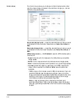
Color screen ............................................................................... 4-4

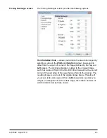
Piking Rectangle screen............................................................. 4-5

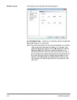
Rotation screen .......................................................................... 4-6

Document Setup screen ............................................................. 4-7

Advanced Color screen .............................................................. 4-9

Multifeed screen ....................................................................... 4-10

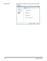
About screen ............................................................................ 4-12

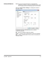
This chapter provides information about advanced features that can be 
used with 

Kodak Ngenuity

 9000 Series Scanners. The controls for 

operating the Advanced Features are accessible within the 

VirtualReScan

®

 (VRS) Interactive Viewer. 

NOTE: When VRS is not installed, similar settings can be found in the 

Direct ISIS and TWAIN settings.

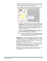
The features on the Advanced Properties dialog box can be used to 
control scanner-specific features that are not accessible through the 
Kofax VRS or scanning application screens. The general rule for VRS 
integrations is that if there is a control for a feature in both VRS and in 
the Advanced Properties dialog box, then the VRS control’s setting will 
override the setting in the Advanced Properties dialog box. For 
example, if you have health forms where you need to drop out a form 
color or if you have documents with labels that cause false multifeed 
alarms, etc., you can change the scanner’s settings on the Advanced 
Properties dialog box to enable Multifeed detection or electronic color 
dropout scanner features. These settings can be saved as part of a 
profile. Any settings made on the Advanced Settings screen will 
override the same settings defined in a saved profile. For more 
information on scanning with VRS Test Application and Profiles, see the 
Kofax VRS 4.5 (or newer) User’s Guide.

NOTE: Any settings made in the Advanced Properties dialog box must 

be saved in a profile or they will be lost when the application is 
closed.

Some of the settings that can be made using the Advanced Properties 
dialog box include: color dropout, multifeed, rotation, document setup 
(i.e. allowing for large skew, etc.) 

Summary of Contents for Ngenuity 9090DB

Page 1: ......

Page 2: ...t disassemble service or modify the scanner except as explained in the User s Guide Do not move the scanner with the power cord and interface cable attached This may cause damage to the cord cable Rem...

Page 3: ...OVERVIEW 1 1 INSTALLATION 2 1 CONTROL PANEL AND NGENUITY OPERATOR UTILITY 3 1 ADVANCED FEATURES 4 1 MAINTENANCE 5 1 TROUBLESHOOTING 6 1 APPENDICES A C...

Page 4: ...s 90 pages per minute in color grayscale or black and white in landscape mode Kodak Ngenuity 9090DB Scanner duplex scanner that scans 90 pages per minute in black and white in landscape mode Kodak Nge...

Page 5: ...canned images CAT No 863 4230 What s in the box Kodak Ngenuity 9090DC 9090DB 9125 or 9150 Scanner 10 foot power cord and USB cable Camera calibration kit Starter cleaning kit Kodak Ngenuity Series Sca...

Page 6: ...eeder table extender provides a support for longer documents that extend beyond the standard length The extender can be pulled out to add approximately 7 inches 18 cm to the feeder table 5 Document fe...

Page 7: ...standing in the front of the scanner to release and open the transport cover 9 Transport cover opens in an upward position and will stay open in a full up position with the support of two gas springs...

Page 8: ...y are in the top slots causing the exit tray to tilt in a downward position This position aids stacking of long documents in the exit tray Tilted Backward tabs at the back of the tray are in the botto...

Page 9: ...ld be folded down when scanning extra long documents that require the use of the exit tray extender NOTE Positioning the document stop guide too close to the back of the exit tray towards the back of...

Page 10: ...ument jam will occur 3 SCSI connector connects an optional SCSI cable cable and SCSI card are not provided 4 USB connector connects the USB cable to the scanner and host PC 5 Fan for cooling the scann...

Page 11: ...t then the Ngenuity Operator Utility NOU Do not reboot the host PC after installing each software application NOTE For the latest drivers go to www Kodak com go scanners 5 Power down the host PC 6 Att...

Page 12: ...eighs approximately 112 pounds 50 8 kg Be sure to incorporate the appropriate manpower before moving or lifting the scanner 3 Without the scanner attached turn on the host PC 4 Load the Installation C...

Page 13: ...me Screen default will update when the scanner self tests have passed and communication with the scanner has been established NOTE If the Ngenuity Operator Utility failed to connect with the scanner r...

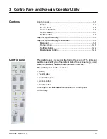
Page 14: ...nu bar 3 9 Home screen 3 10 Settings button 3 12 Maintenance button 3 14 Control panel The control panel is located on the front of the scanner The LEDs and audible tones notify you of the current sta...

Page 15: ...pass through door is closed the rotary path to exit tray is in use LED On when the straight pass through door is open documents being scanned will be exited through the straight pass through door Pow...

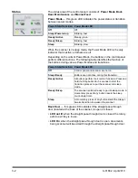
Page 16: ...Manual mode In this mode the paper sensor on the feeder table will trigger the skimmer to pull the documents into the scanner transport This mode can also be used to automatically feed small batches...

Page 17: ...Properties to open the scanning application s Scanner Properties window 6 Select Manual from the Source drop down box 7 Lift the skimmer 8 Remove any paper from the feeder 9 Start a scan either single...

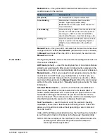
Page 18: ...ore information Scan monitor The Scan Monitor indicates that an error has occurred during scanning The Scan Monitor indicators are lit in yellow Error indicates that an error exists that is not covere...

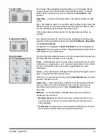
Page 19: ...each multifeed that is detected while scanning For more information see Chapter 4 Advanced Features The MF Ignore button toggles the multifeed ignore feature on and off When it is on the scanner will...

Page 20: ...essing Pause Stop stops the transport before the automatic transport timeout 20 seconds If the scanner is feeding documents pressing Pause Stop once will stop feeding and a host scanner paused error w...

Page 21: ...e displayed on the Home screen of the NOU NOTE The Ngenuity Operator Utility remains accessible but not functional after connectivity with the scanner has been established and then the scanner is powe...

Page 22: ...e you can paste it into another application This will allow you to save the file in another file format if desired Copy to Clipboard is useful for sending the information via E mail for troubleshootin...

Page 23: ...pport dialog box which provides technical support information and links About Scanner Operator Utility displays the About dialog box which provides the Ngenuity Operator Utility application version an...

Page 24: ...ort replace feed rollers etc Monitored maintenance includes Clean feed rollers Clean transport Clean optics e g imaging guides camera glass covers sensors Replace feed rollers Calibration of the front...

Page 25: ...enance Settings button When you click the Settings button on the Ngenuity Operator Utility main screen the Configure Scanner Settings screen will be displayed You can configure basic scanner settings...

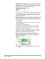
Page 26: ...set the volume of a selected sound that alerts you to an error Volume can be set to Mute Low Medium or High Error Sound one of three sounds can be selected Sound1 Sound2 Sound3 Click Play Sound to he...

Page 27: ...screen Intervals can be set for cleaning the feed rollers skimmer rollers pick and drive and separator roller the transport rollers the optics and to replace the feed rollers skimmer rollers and separ...

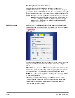
Page 28: ...feature in both VRS and in the Advanced Properties dialog box then the VRS control s setting will override the setting in the Advanced Properties dialog box For example if you have health forms where...

Page 29: ...ications VRS ISIS based Applications VRS TWAIN based Applications NOTE This User s Guide only documents the VRS based scanning setup For scanning applications that utilize the VRS based driver the VRS...

Page 30: ...back page post scan imprinter Clicking the Scanner Driver Settings icon displays the Advanced Properties window To display the functions contained within a menu click the corresponding hyperlink OK s...

Page 31: ...still produces acceptable image quality Better some compression which produces decent image quality Best minimal compression which produces very good image quality Custom select this option to custom...

Page 32: ...age defined by the Top and Left values The picking rectangle is relative to the cropped image such that a value of Top 0 00 and Left 0 00 will always be the very left corner of the lead edge of the pa...

Page 33: ...r this rotation For example if the Advanced Properties rotation is set to 90 degrees for both the Front and Rear and VRS auto cropping is enabled and a document with text on the front and only a photo...

Page 34: ...ly tear Thick or Envelope for scanning thick paper or envelopes Tri Fold for scanning tri fold documents NOTE Document types other than Normal may reduce scanner speed Allow Large Skew if enabled this...

Page 35: ...image when scanning in black and white or grayscale only This control is not supported when scanning in color Conflicting Controls Resolution Single Page Scan The scan is terminated and an error mess...

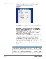
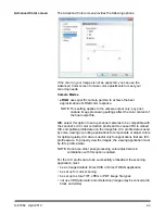
Page 36: ...s ICC color correction profile and to cause VRS to embed ICC compatible profile data into the image file ICC profile data is used by some viewing or printing applications to compensate or adjust colo...

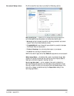
Page 37: ...t the default value of 1 3 NOTE Selecting one of these Camera Mode options activates that option for both the front and back camera Multifeed screen The Multifeed screen provides the following options...

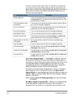
Page 38: ...ject the multifeed document and continue scanning keeping the multifeed image NOTE If the scanner s audio feature has been set to Mute you will not hear the alarm that occurs with the Notify and Stop...

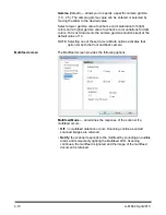
Page 39: ...4 12 A 61662 April 2010 About screen The About screen displays the scanner version and copyright information...

Page 40: ...ables 5 17 Keeping the scanner s hardware and software versions current along with performing routine maintenance will ensure optimal image quality and prolong the life of your scanner The Maintenance...

Page 41: ...eeder jams Clean transport rollers 50 000 pages 5K 100K Multifeeds Transport jams Elongated images Clean Optics imaging guides cameras glass covers sen sors Optics does not include lamps The lamps LED...

Page 42: ...bber tires on the skimmer module and separator roller is normal Tire debris does not always mean that the tires are worn or damaged After cleaning inspect the tires for wear and replace the separator...

Page 43: ...for correctly installing the tires on the roller and also the rollers into the skimmer housing When installing the tires the 3 dots should always be facing left If the tires or rollers are installed i...

Page 44: ...leaning wipe scrub the roller tires in a side to side motion Rotate the roller to clean the entire surface 4 Re install the clean pick roller With the pick roller positioned so the dots are facing the...

Page 45: ...e entire surface of the tires 7 Re install the drive roller With the drive roller positioned so the dots are facing the left side slide the roller onto the right drive roller shaft Angle the right sid...

Page 46: ...n the separator roller correctly with the slots Align the flat end of the shaft with the slot in the cradle and gently seat the shaft which should fall in place Do not apply pressure to seat the shaft...

Page 47: ...are located in the top and bottom transport trays When removing a imaging guide for cleaning or replacement the entire assembly imaging guide and frame are removed and replaced as one piece Clean the...

Page 48: ...Do not spray sol vent in or around the internal components of the scanner 7 When the camera cover is clean re insert the cleaned imaging guide into the scanner by holding the frame of the imaging gui...

Page 49: ...n tube on the can to spray the forced air Do not turn the can upside down or tip it sideways 10 Feeder sensor Place the brush end of the blower brush into the feeder sensor area and squeeze the blower...

Page 50: ...nto the exit sensor area and squeeze the blower brush several times 13 When all sensors are clean close the transport cover and reset the maintenance reminder by clicking on the Clean Optics hyperlink...

Page 51: ...to Feed Test Batch This will start the scanner transport By default the F1 key is assigned the Feed Test Batch function 4 Feed the transport cleaning sheet in landscape orientation into the scanner tr...

Page 52: ...shaft leaving the shaft in the same position as a reference for putting on the new tires NOTE Another point of reference for correctly installing the tires is the side of the tire containing the dots...

Page 53: ...lots Align the flat end of the shaft with the slot in the cradle and gently seat the shaft which should fall in place Do not apply pressure to seat the shaft 12 Gently release the separator roller doo...

Page 54: ...st the life of the scanner with normal use If something happens that requires the replacement of the LEDs contact Kodak Technical Support Camera calibration Before calibrating clean the scanner optics...

Page 55: ...NOTES Do NOT open the scanner cover or shut down the scanner or host PC while calibration is in progress Do NOT manipulate any software applications on the host PC or other host PC controls while cali...

Page 56: ...les go to www kodak com go scannersupplies Supplies Consumables CAT No Small Roller Kit 176 6674 Medium Roller Kit Includes 24 skimmer rollers 6 separator rollers 844 3491 Large Roller Kit 115 8153 Cl...

Page 57: ...l the scanner transport cover release lever forward to open the transport cover 2 Remove any jammed document s from the transport NOTE If the document is in several pieces carefully inspect the entire...

Page 58: ...stall the SCSI card from the host PC Error Message Possible Cause Possible Remedy Self Test Error Messages Feeder Table Fault The stack of documents in the feeder table is too heavy Remove some of the...

Page 59: ...n the transport area Clean the transport sensors See Chapter 5 Maintenance Entry exit sensor errors Transport sensors need cleaning Clean the transport sensors See Chapter 5 Maintenance Feeder table d...

Page 60: ...nt Onboard Ngenuity VRS 4 5 or greater Professional Interface USB 2 0 cable included SCSI III D68 SCSI 3 Support drivers included ImageControls ISIS TWAIN Multifeed detection Ultrasonic multifeed feat...

Page 61: ...ystem Microsoft Windows 2000 Professional with SP4 Microsoft Windows XP Professional with SP2 Microsoft Windows Vista Business Feature Specification Power requirements AC 100 120 V 220 240 V 60 50 Hz...

Page 62: ...sition software B 10 This appendix provides installation procedures maintenance and instructions for using the front page pre scan and back page post scan imprinter Front page pre scan imprinting prin...

Page 63: ...the ink cartridge is properly seated 1 Remove the imprinter and ink cartridge from the box 2 Remove the protective tape from the ink cartridge Item Specifications Maximum number of charac ters 72 cha...

Page 64: ...he scanner exit tray 7 Open the front page imprinter door 8 Insert the imprinter s spring loaded locating pin into the correspond ing hole found in the scanner s front page assembly left side with the...

Page 65: ...gnized NOTE Do not leave the ink cartridge in the imprinter when not in use Removing the front imprinter 1 Turn off the scanner 2 Remove the exit tray 3 Open the front page imprinter door 4 Unplug the...

Page 66: ...tion 4 Hold the ink cartridge holder with one hand and place the ink cartridge bottom end first into the holder and snap into place 5 Turn off the scanner and power down the PC 6 Open the back page im...

Page 67: ...o not leave the ink cartridge in the imprinter when not in use Removing the back imprinter 1 Turn off the scanner 2 Open the back page imprinter door 3 Unplug the imprinter cable 4 Unscrew the thumb s...

Page 68: ...rotective tape from the new ink cartridge 5 Move the ink cartridge carriage to the center position 6 Hold the ink cartridge holder and place the ink cartridge bottom end first into the holder and snap...

Page 69: ...r 3 1 Turn off the scanner 2 Remove the front or back imprinter unit from the scanner See the sections entitled Removing the front imprinter or Removing the back imprinter earlier in this chapter for...

Page 70: ...ice Representative for spit pad replacement Using the imprinter Imprinter operation is controlled via the hardware and software Print position hardware To print a string on the scanned document adjust...

Page 71: ...int on the document Print position software To set up the software for imprinting access the Advanced Properties screen which is accessible within Virtual ReScan VRS Interactive Viewer Scanning applic...

Page 72: ...ings icon tools image 4 In the Advanced Properties screen click on the Imprinter menu item to display the Imprinter controls 5 Enable the imprinter you want to use Front Page Prescan or Back Page Post...

Page 73: ...ion allows you to set the document count for the next document that will be scanned Step Amount select a value from the drop down list to determine how the automatic imprinter annotation counter is in...

Page 74: ...on to the scanner is established Special Content select special content format codes to include in the text string from the drop down list These codes are replaced with actual symbols or text by the s...

Page 75: ...ion text will look with any optional date and time stamp special content or page counter expanded When a date and time format is specified the current date and time are applied Imprinter Annotation Po...

Page 76: ...or the offset 2 In the Offset from Top text box specify the distance from the top edge of the page the annotation string should appear This value also controls the mechanical imprinter text offset 3 S...

Page 77: ...that fails to pass through the scanner transport and exit into the exit tray Scan source the scanner selected for use through the scanning application on the host PC Ngenuity Operator Utility NOU the...

Page 78: ......

Reviews: