background image

NovaJet 800 Series Training Guide 


35


Technical Bulletin 2 

Dry Time Guidelines - Printer in Auto Take-up Mode 


The NovaJet 800/KODAK 4800 series printers are considered some of the fastest 
inkjet printers in the market.  Consequently, certain images, using high-speed pass 
settings, may not have enough time to dry before being automatically rolled up on 
the take-up assembly. This is usually determined by the ink lay down percentage. 
Though a typical image would only use 150% ink lay down, some images that use 
more ink may require a slower print speed to use the auto take-up feature. The 
following chart is intended as a general guideline to monitor the output or indicate 
precautionary measures should be taken. Your results will vary depending upon 
environmental conditions, ink loading, media, and printer settings. 
 

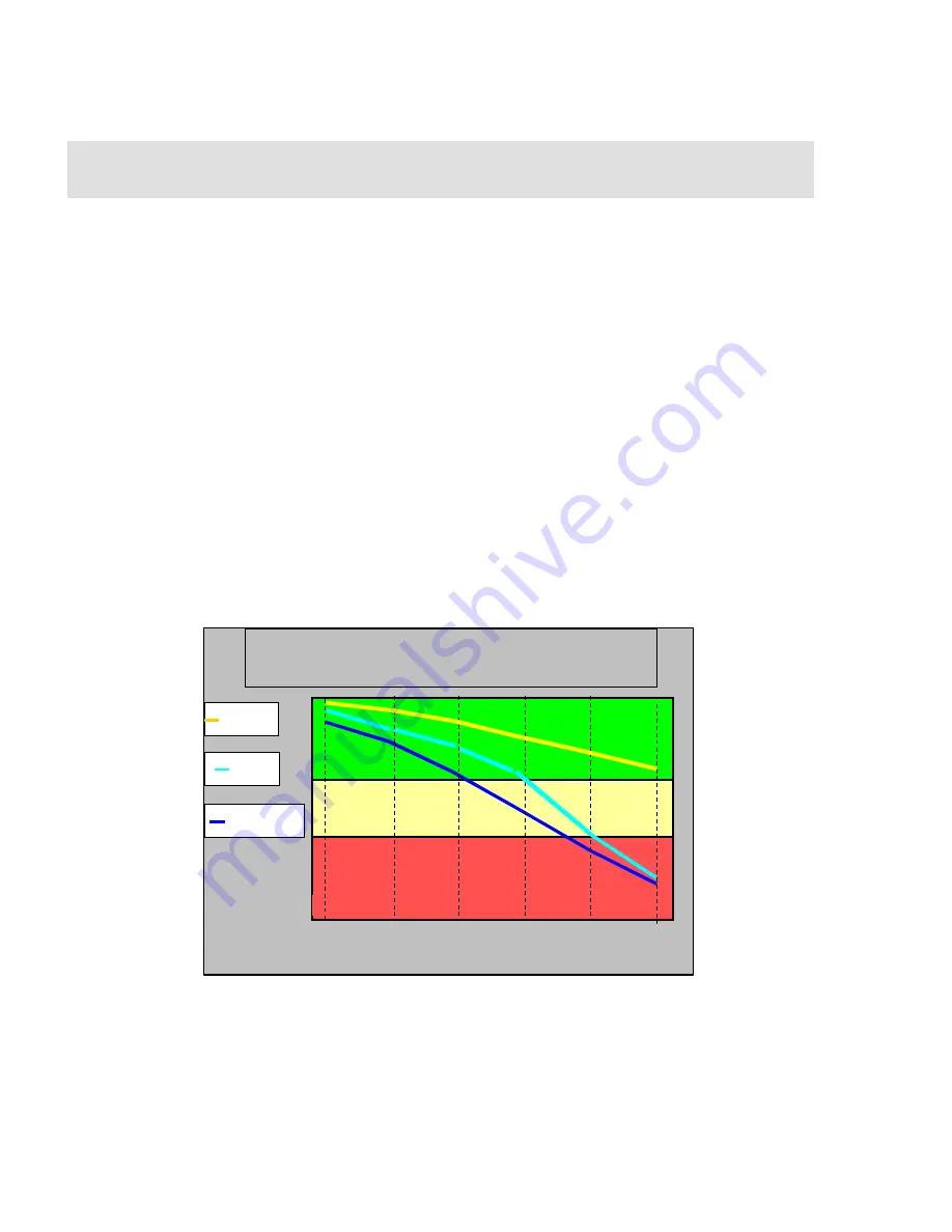
Example of results for KODAK Production Photographic Glossy Paper with 200% ink 
load: 

The printer is set to Photo Mode (

2x4 cartridge set, 3-pass print mode @ speed 10

with the 

Dryer


ON – Heat setting of 100%.

 Printing using GS+ ink at 200% ink lay 

down, the GS+ line (the blue line) is passing through red area of the chart. This 
indicates there will not be enough time to completely dry the print before reaching 
the Automatic Take-up.  Precautionary measures should be taken to insure that the 
image would not be damaged.  Usually this would simply require selecting a 
slower print speed at the printer (If you are not familiar with this feature, please 
refer to the User Guide CD to select print speeds. Also refer to 

Print Mode 

Comparisons

 at the end of this document for real world printing 

operations/applications) 


NOTE:


These recommendations are based upon printing in conditions of 50% to 65% relative 

humidity (RH) and at ambient temperature (72° F, 22° C).   You may experience different results if 
your temperature and humidity values are different.   If your RH is less than 50%, you can expect 
much faster dry times.  If your RH is greater than 65%, your dry times will normally be longer.  

The above chart is intended as a general guideline. 

% Ink Lay Down 


GS PLUS 

GX 

GO 

GO 

Images may not be able to use full speed take-up 

10

0%

12

5%

15

0%

17

5%

20

0%

22

5%

Take-up may be used at full speed 

Most images may use take-up at  full speed 

Take-up & Dry Time 

50% to 65% Relative Humidity, 22 deg C (77F) 

Summary of Contents for NovaJet 850

Page 1: ...Ink Installation 6 Printer Calibrations 11 Networking 18 Routine Maintenance 19 Preventive Maintenance 23 Cartridge Checklist 24 Common Problems 25 Technical Bulletins Available Ink Configurations Dry Time Guidelines Routine Printer Maintenance NJ880 Rigid Textile Print Ops Printer Grounding ESD Control Output Symptoms 34 34 35 38 38 43 ...

Page 2: ... feed system media rollers media core 2 media adapters dryer 2 dryer brackets dryer logic cable and Ink Prime box Box 3 is the accessory box which contains the ink and cartridges sample roll of media cutters and all versions of power cords NOTE You will need to provide an RJ45 Ethernet cable to connect to the Ethernet port 2 Remove all contents from Box 2 2nd largest box Box 2 contains the stand l...

Page 3: ...eservoirs 12 cartridge tubing needles septum connectors network parallel cable and documentation 4 Attach legs and feet to printer Caution Do not damage leg harness wiring Ensure cable is not pinched twisted 5 Rotate printer to one side and lift out of box using a two person lift Ensure all plug connections are intact ...

Page 4: ...nitially pulse in one direction By blocking either the top sensor or bottom sensor path the opposite roller should reverse direction Dryer should intermittent pulse every few seconds after 5 minutes the air leaving the dryer should be warm Prime Color Calib Menu Access Cartridge Display Settings Service Menu Print Settings Calibration Menu Exit Utility Menu Calibration Menu Diagnostics Menu About ...

Page 5: ...ipe Save Media Paper Option Menu Exit Supply Type Take up Next Option Cancel Print Passes Ok Prev Option Press Next Option until Take up is displayed select Ok Auto Load Delay 9 Select supply mode Options include Sheet Roll Roll 2 or Take Up 10 Load media into printer Ensure alignment guides are set properly Note maximum weight of media roll is 60 pounds Verify media loads correctly and is measure...

Page 6: ...ge characteristics 2 Installing ink into reservoirs It is suggested to fill reservoirs over a table to prevent spills on printer fill to a maximum of 400 ml 50 ml minimum 3 Attach septum fitting to valve body Prime line and cartridge if necessary NOTE When the valve body is raised to the up position ink flow is cut off when the valve body latch is closed then the ink line is open ...

Page 7: ...head using multiple sets of one second bursts until ink is visible in the ink line This may take 1 2 minutes to accomplish depending on the prime of entire ink line Ensure EasyPrime adapter is flush to cartridge jet plate a siphoning sound slight sucking should be heard when priming the cartridge properly 4 Activate the color test pattern for ink starvation problems Select SETUP MENU PRINT MODE ME...

Page 8: ...elow NOTE If you are installing a new Warranty print head empty need to revive a deprimed cartridge due to ink starvation problems see H 11 on page 30 for example or to verify proper cartridge ink levels obtain syringe with extension tube from accessory kit Pull 20 ml of ink into syringe from ink reservoir or new ink bottle Lift cartridge stall position valve to up position to cut off ink flow NJ7...

Page 9: ...jet compensation is provided up to 20 jets in each cartridge Ensure the integrity of the diagonal lines are consistent and smooth Clean or replace cartridge if unsatisfactory 6 Manually Bypassing Cartridge Jets A manually bypassed jet appears as an 80 filled block in the prime pattern see jets at left and right below Perform manual jet bypass whenever a jet illustrates degraded performance i e clo...

Page 10: ...Ok Black Edit List Press Next Option until clogged jet number is displayed press Toggle Jet to turn jet OFF press OK Blown Jets To manually bypass a clogged black i e K jet perform the following steps In the example below the Magenta jets are illustrated completely blown 100 filled blocks but are being automatically bypassed by the printer There is no need to manually bypass any of the jets seen h...

Page 11: ...nches or 838 mm and another T will be printed This calibration is extremely important for paneling and framing operations to ensure proper line length accuracy printer accuracy is guaranteed to 0 2 Cut off and measure the distance between the two T s using a draftsman ruler enter the true value under under Paper Axis Select Utility Menu Calibration Menu Paper Axis enter the true value once only No...

Page 12: ...ayed select Ok Re run the Slow Db Test again to check Repeat until pattern is correct This printed pattern is correctly adjusted Deadband Test Single Line Test All Lines Test Slow Db Test Deadband Exit Slow Deadband Calibration Menu 2 Slow Deadband Calibration To activate the Slow Deadband calibration select Utility Menu Service Menu Calibration Menu Slow Db Test The Slow dB Test pattern will prin...

Page 13: ...ue Press Next or Prev Option until 68 is displayed select Ok 3 Color Deadband Calibration To activate the Color Deadband calibration select Utility Menu Calibration Menu Color dB Menu Color dB Test The Color dB pattern will print This is an electronic calibration for compensating the differences in cartridge resistances Always perform this calibration whenever a cartridge is replaced To adjust lef...

Page 14: ...iz Calib Test will need to be activated and adjusted Seven horizontal patterns followed by seven vertical patterns will print The color calibration pattern should be performed whenever a cartridge is removed from the carriage for cleaning or replacement Choose the best value under each aligning set of colors i e yellow to magenta then magenta to cyan then cyan to black Enter the most correct value...

Page 15: ... are designed with self aligning pinch rollers The alignment process takes place when media is advancing forward but not backwards Loading media is critical to the media alignment and reducing skew Many times the media is loaded at a slight skew and will take several feet of advancing media to get it aligned properly This can be improved by following the steps below 1 Load the media and align the ...

Page 16: ...s defined in the user manual have been followed Exhibit A describes the maximum permissible image skew The maximum skew is 0 30 of L L1 L2 except for NJ880 no skew specification has been designated Example If LW 59 61 inches 1 51 m L 48 00 inches 1 22 m Then L1 should equal L2 76 53 inches 1 94 m The actual permissible skew L1 L2 003 76 53 229 5 82 mm NOTE This is the only method used to determine...

Page 17: ...ption Press Next Option until Ten is displayed select Ok 8 Best Quality Mode To obtain the highest or optimum print quality mode from the printer for 1x4 or 1x8 operations place the print pass mode to 10 carriage speed of 7 and bi directional operation For 2x4 print operations place the print pass mode to 5 To set the print pass mode Print pass mode will impact image output quality refer to the gu...

Page 18: ...ction icon When the Local Area Connection dialog box opens double click on the TCP IP protocol to activate the TCP IP properties See figure below 2 Assign TCP IP address at printer stay in the same range as host computer from step 1 Select Setup Menu Network Menu Ensure DHCP is disabled unless advised by a network administrator that it is required may also need to install configure a standard TCP ...

Page 19: ...illed Water Apply solution to lint free towel and thoroughly clean platen surfaces printing area and cutter groove bottom surface Use a toothpick to help remove residue debris from the cutter groove If the cutter groove is not cleaned adequately this can lead to paper sensing errors resulting in no printing symptoms Using a toothpick ensure the platen vacuum holes are free of obstructions INTERVAL...

Page 20: ... deprime occurs the cartridge will need to be re primed using the NovaPrime or EasyPrime device Apply solution to a 2nd lint free towel thoroughly wipe the electrical cable contacts at rear of cartridge Proceed to flex driver cable cleaning prior to attaching cartridge see below INTERVAL COMPONENT CLEANING AGENT 75 Plot Hours Flex Driver Cables NovaKlean Isopropyl Alcohol Apply solution to lint fr...

Page 21: ...mon symptom attributed to a dirty encoder strip or encoder sensor INTERVAL COMPONENT CLEANING AGENT 75 Plot Hours Trailing Cable Soapy Water only Apply solution to lint free towel Clean entire length of both trailing cable surfaces ensure the upper and lower portions of both cables are thoroughly cleaned No residues i e tacky surface etc should remain Clean the top surface of the encoder stabilize...

Page 22: ...wel Clean entire surface area around the bushing Repeat for the opposite side of carriage assembly NOTE Refer to Preventive Maintenance on last page of this document INTERVAL COMPONENT CLEANING AGENT 75 Plot Hours Pinch Lower Roller NovaKlean Distilled Water Apply solution to lint free towel Clean entire surface area of upper pinch roller and remove residues on lower roller NOTE if residues i e vi...

Page 23: ...wab against sensor surfaces transmitter and receiver to clean Alternative procedure Remove the service station Push carriage assembly partially over the service station access hole Apply solution to a lint free towel Using one hand with towel maneuver lint free towel down and underneath the carriage assembly blot both sensor surfaces located 4 mm behind right carriage assembly Magenta flex driver ...

Page 24: ...contacts Multiple Power and Address line failures one cartridge is defective use post it note technique to isolate defective cartridge A clogged jet is illustrated as jet 111 jets 105 and 108 are manually bypassed 80 filled blocks only Jet 114 is defective and is automatically being bypassed Between 20 and 35 jets in each color may be defective or bypassed to maintain photo quality printing 2 Micr...

Page 25: ...0i Technical Bulletin 5 for similar procedure Replace encoder strip service required if problem cannot be corrected 2 Missing data in an image is typically a print server or network traffic problem Increase data port rate or reconfigure print server 3 Multiple lines throughout a print typically indicates a problem with the connectivity to the printer Ensure only an IEEE compliant parallel printer ...

Page 26: ...rriage delayed printing hesitation Hesitation of the carriage assembly during printing can be due to various factors i e Slow processor in workstation for Software RIPs screen saver turned on improperly configured parallel port for non networked environments incorrect speed setting for driver data transfer rate Firewall interference print server setup untested print server used incorrect SEH setup...

Page 27: ... ml of ink inside Printer stand surface or floor area must be level and flat 8 Microbanding is typically caused by incorrect printer calibrations or low pass printing Print pass modes of 4 or lower may cause banding refer to Section C 8 above Ensure all calibrations are performed correctly Defective or clogged cartridges may also cause micro banding Perform printer calibrations and replace associa...

Page 28: ...onsistency Up to 20 jets may be compensated in each cartridge while maintaining photo pass quality printing 9 Horizontal bands along the right edge of the media are typically caused by a dirty service station or cartridge Curling media from high humidity or media too thick can also cause the banding problem ...

Page 29: ...ically caused by inadequate cartridge priming or a leak in the ink delivery system Ensure the cartridge has been properly primed using the NovaPrime or EasyPrime device Ensure all septum connectors are tightened securely Refill cartridge to 20 ml of ink and reprime cartridge establish negative pressure Replace septum connectors tubing needles if cracked broken replace cartridge 12 Text errors or l...

Page 30: ...Vertical banding can also be caused by a defective trailing cable or when ink saturations are extremely high 290 and the dryer is used with high heat applied 14 Unusual patterns which print in either the Prime pattern lower left illustration or in normal prints lower right illustration are symptoms of a defective trailing cable Replace the trailing cable service required To prevent these failures ...

Page 31: ...alization then turns off LED staying on would indicate a problem when the FPGA is not configured Ensures the gate array chips have been properly programmed one on Main PWA and on each Carriage PWA D8 24V available D13 5V available Check the Boot Code for proper initialization While holding down the two buttons indicated below turn on the printer a cyclical two beep sequence should be heard 16 For ...

Page 32: ...ervice Menu Diagnostic Menu Accessory Menu Sensor Status The printer LCD will display the following information Dryer Mode cccccccc Plenum T deg C MBoard T deg C MBoard H pct RH The Dryer Mode cccccccc indicates the current dryer setting Operational modes are OFF ON Heat AUTO FANS ONLY No Heat or DISABLED error condition Plenum T and MBoard T main board T indicate temperature and are displayed in ...

Page 33: ...s and printer reboots The carriage bushings are excessively dirty or worn clean or replace carriage bushings 4 or 6 depending on the previous service action During printing and prior to the error message a common symptom resembles rainbow or data shift problems similar to those pictured below erratic non smooth carriage movement may also be observed during these mis prints ...

Page 34: ...ed to be primed and working correctly in these unused locations While the stall positions are not used during printing they are used during routine spitting i e every 6 15 or 120 second spit intervals depending on ink type and spit routine selected An Out of Ink or Deprime error message may result if cartridges in these stall positions are not primed properly as outlined above NOTE 2 The Kodak 480...

Page 35: ...ink at 200 ink lay down the GS line the blue line is passing through red area of the chart This indicates there will not be enough time to completely dry the print before reaching the Automatic Take up Precautionary measures should be taken to insure that the image would not be damaged Usually this would simply require selecting a slower print speed at the printer If you are not familiar with this...

Page 36: ...e deformation issues i e vertical banding may be encountered due to excessive heat temperature If a problem is encountered place the Dryer setting to ON and choose a specific Heat Setting value i e change from 100 to 60 run a test print to determine the optimum drying temperature for your specific media at given saturation level Please refer to the on line Media Technical Data sheets for specific ...

Page 37: ... cartridge set running 6 pass print mode has significantly better quality than the 2x4 cartridge set running 3 pass print mode Also the 1x4 6 pass has better quality than 2x4 4 pass as well The 1x8 cartridge set running 6 pass uses 20 30 more inks vs 1x4 cartridge set running 6 pass but print time is about the same Across a broad range of tested images customers have observed an increase of ink us...

Page 38: ...l printer performance 1 Equipment Note Transfer of Rigid Media 1 Three or four ball bearing stands are suggested for use with the NJ880 but are not provided The ball bearing stands from McMaster Carr have been tested as being one of the best for the price part number 5904k3 42 99 each Other similar stands are available but have not functioned as well during testing Orient two stands in front and t...

Page 39: ...Roll Mode Feeder Stop Mode A The Roll mode take up is default should only be used to load rigid media The Sheet mode will advance media out of the printer at the end of a print job possibly causing damage to the print Select Setup Menu Paper Option Menu Supply Type choose Roll and press Ok B The Feeder Stop mode default must be changed to Normal or the printer will think it is out of paper after 1...

Page 40: ...ause the media to bind and stop feeding through the NovaJet 880 If the feather board is used it will have to be mounted to the flattening roller assembly in such a way as not to cause media path damage NOTE Some customers have found using 2 very strong magnets works well too Plastic feather board used to control heavy rigid board feed http www mcfeelys com subcat asp subcat 16 5 7 Application Note...

Page 41: ...red The sprayer used in our work is a high volume low pressure HVLP unit The spray nozzle is a typical gun type sprayer without any special nozzle The number of passes or layers of coating required depends on the media being coated The more porous the media the greater amount of coating required Media coated successfully with the undercoat include FoamCore Coroplast and plywood A primer coat for g...

Page 42: ...nter will pull the media through the printer While a lighter piece of media i e Foam Core that is flat may perform fine a thinner but heavier piece of media i e 3 8 Sintra may not feed through the printer due to a slight warp in the media Please refer to the media deviation and weight standards table below 10 Application Note Waterproofing Outdoor Prints Digital printing has a durability problem o...

Page 43: ... the power and grounding scheme at the installation facility A second issue would be the lack of electrostatic discharge ESD protection Without proper grounding the ESD brushes are rendered useless A higher incidence of cartridge failures will occur if adequate grounding not properly supplied as well as possible malfunctions of printer s electronic circuitry Review sections A E A Symptoms of ESD E...

Page 44: ...ation values may be consistently too low i e 4840 to 4870 Typical feed adjust should be 4800 15 for most media types Media which generates a high amount of static electricity i e 15 000 30 000 volts and is thin i e 3 mil may be subject to improper transfer through the printer s media path often referred to as media static cling NOTE To isolate a suspected media type load a different the media type...

Page 45: ...discharges from media printer to the cartridge jet plates can cause premature failure of internal cartridge electronics i e Poly Poster Polyethylene lumatrans duratrans or similar plastic film media is commonly known to release static charges during media feed NOTE the failure of one cartridge can cause other cartridges to appear as failures contact technical support to diagnose correct cartridge ...

Page 46: ...uld typically be between 45 and 55 in a normal room temperature environment for the best printing results ESD suppression and color control The suggested optimum temperature range for print environments is 68 72 degree F 20 22 2 degrees C 3 Installation of Rear Anti Static ESD Brush contact technical support if an ESD Field Installation Kit is determined to be necessary based on your specific regi...

Page 47: ... actually touch the media Fig A NOTE 2 align ESD brush bracket to extreme rear edge of platen allow brush to extend approximately 0 25 7 mm from rear surface of platen The carbon brushes should be 0 10 2 54 mm to 0 25 6 35 mm from the media surface when media is loaded Refer to Figure B below Tip The brush bracket can be more easily aligned by pushing the bracket up against the exhaust grill s on ...

Page 48: ...er will basically function but can cause a safety hazard if a person touches the printer chassis and another electrical device such as a computer The voltage on the chassis can be raised to a level of approximately half the input AC voltage The installer should always validate the power and grounding scheme at the installation facility A second issue would be the lack of electrostatic discharge ES...

Page 49: ...ervice technicians should attempt to perform Step 1 below It is strongly suggested to contact a certified electrician if a test method or measured value is not completely understood 1 Testing AC level on printer chassis Turn on Printer With meter in an AC scale connect both the black and red leads to the printer s rear metal plate screws at rear of printer The normal chassis AC voltage reading wit...

Page 50: ... Do not operate work on printer if a 3 prong to 2 prong adapter non grounded standard receptacle non grounded GFCI receptacle or a separate ground line runs from the printer Contact technical support management if necessary for intervention assistance 3 Testing Receptacle Neutral to Ground Voltage In North America the easiest and safest test method is to use a receptacle tester i e available at Ho...

Page 51: ...n will need to be contacted to upgrade the electrical system with a properly grounded outlet or to correct a neutral to ground voltage problem D Power Voltage Testers 1 In North America basic receptacle testers are available for testing standard 110 volt receptacle wall outlets for proper polarity and ground detection These models are probably the fastest and safest way in detecting improper wirin...

Page 52: ...rference currents Lead resistance transforms these currents into voltage fluctuations As a consequence of ground loop induced voltages the ground reference in the system is no longer a stable potential so signals ride on the noise The noise becomes part of the program signal Ground loop is a common wiring condition where a ground current may take more than one path to return to the grounding elect...

Page 53: ...stallation of these types of adapters provides an extremely unreliable ground is dangerous to the operator and equipment and should never be considered a solution c Non Grounded Conditioners Regulators Never connect a line conditioner or power regulator to an ungrounded power source this can be dangerous to the equipment and operator See b above DISCLAIMER This technical bulletin has been provided...

Reviews: