


Installation Guide
4-3
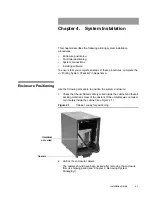
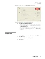
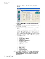
Chapter 4. System Installation
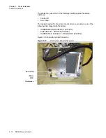
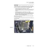
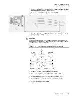
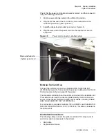
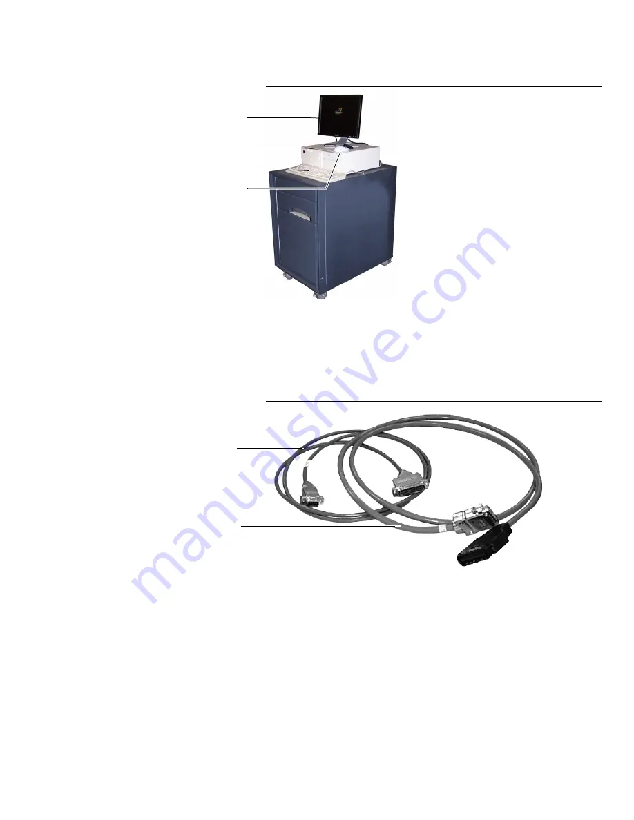
Controller Positioning
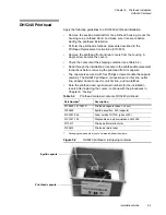
Figure 4.3
Controller components on system enclosure
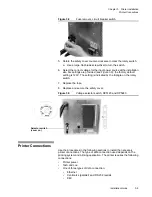
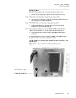
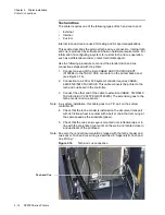
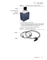
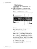
7. Unpack the system accessories box.
8. Disconnect the retaining cable attaching the printer rear panel to the
enclosure. The retaining cable secures the printer during shipping,
but prevents it from being pulled out for service access.
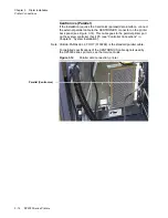
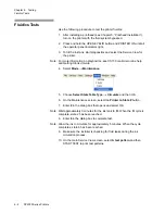
9. Set all the cables aside for later use (see Figure 4.4).
Figure 4.4
Hardware and cable kit cables
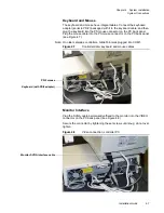
Controller PC (chassis)
Monitor
Keyboard
Mouse and pad
0139601
0139268
Summary of Contents for VERSAMARK DP5120
Page 1: ...Versamark DP5000 Series Printers DP5120 DP5122 and DP5240 Installation Guide ...
Page 2: ......
Page 3: ...Versamark DP5000 Series Printers DP5120 DP5240 and DP5122 Installation Guide ...
Page 8: ......
Page 12: ...Contents Figures 4 DP5000 Series Printers ...
Page 14: ...Contents Tables 4 DP5000 Series Printers ...
Page 32: ...2 16 DP5000 Series Printers Chapter 2 Unpacking Printheads ...
Page 52: ...3 20 DP5000 Series Printers Chapter 3 Printer Installation Printer Connections ...
Page 76: ...B 2 DP5000 Series Printers Appendix B Tach and Cue Wiring ...
Page 80: ...C 4 DP5000 Series Printers Appendix C Site Requirements Space Requirements ...
Page 81: ......


