


4-4
DP5000 Series Printers
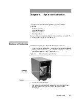
Chapter 4. System Installation
System Connections
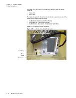
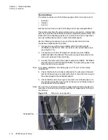
System Connections
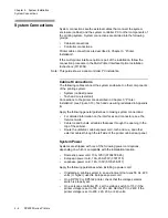
System connections are the external cables that connect the system
enclosure (cabinet) and the system controller PC to other components of
the printing system. System connections are divided into the following
groups:
•
Cabinet connections
•
Controller connections.
Printer cable connections are described in Chapter 3, “Printer
Installation”.
If the multi-printer interface option is part of the installation, follow the
connection procedure in the Multi-Printer Interface Option
Installation
Instructions
(0114054).
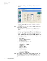
Note: This guide shows a dual-controller PC installation.
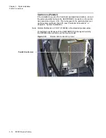
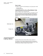
Cabinet Connections
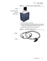
The following cables connect the system enclosure to other components
of the printing system:
•
System (cabinet) power
•
Tach and cue (external).
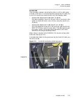
Connections to the printer are described in Chapter 3, “Printer
Installation” (see Figure 3.10). Tach and cue wiring is detailed in Appendix
B.
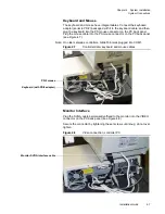
Apply the following general guidelines to making system connections:
•
For detailed information on the interfaces and connectors, see the
Service Guide
.
•
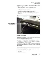
Cable tie and bundle all cables that pass through the opening in the
top of the cabinet.
•
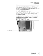
Route the umbilical, cabinet power cord, tach and cue, and other
external cables through the left side of the printer cabinet rear panel.
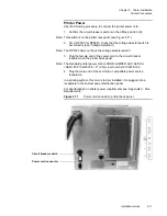
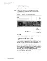
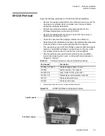
System Power
Systems are shipped with one of the following power cord options,
depending on which is compatible with the installation location.
•
Domestic power cord, 13A, 125V (0100238-026)
•
European power cord, 10A, 200-230V (0181015)
•
Japanese power cord, 12A, 100V (0100238-017).
Apply the following guidelines when installing a power cord:
•
If installing a printing system in an environment that uses 50 Hz, 220
volts (or higher), use the European power cord.
•
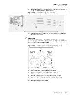
On a DP5120 or DP5122 printer, check that the voltage selector
switch is properly set.
•
On a Jetscape controller PC, set the voltage switch to 115V if the
printer voltage is set to 100 or 120 volts. Set the PC to 240V if the
printer voltage is set to 200, 220, 230, or 240 volts.
Summary of Contents for VERSAMARK DP5120
Page 1: ...Versamark DP5000 Series Printers DP5120 DP5122 and DP5240 Installation Guide ...
Page 2: ......
Page 3: ...Versamark DP5000 Series Printers DP5120 DP5240 and DP5122 Installation Guide ...
Page 8: ......
Page 12: ...Contents Figures 4 DP5000 Series Printers ...
Page 14: ...Contents Tables 4 DP5000 Series Printers ...
Page 32: ...2 16 DP5000 Series Printers Chapter 2 Unpacking Printheads ...
Page 52: ...3 20 DP5000 Series Printers Chapter 3 Printer Installation Printer Connections ...
Page 76: ...B 2 DP5000 Series Printers Appendix B Tach and Cue Wiring ...
Page 80: ...C 4 DP5000 Series Printers Appendix C Site Requirements Space Requirements ...
Page 81: ......