


4-6
DP5000 Series Printers
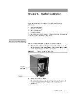
Chapter 4. System Installation
System Connections
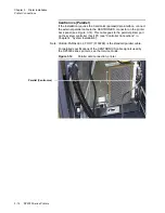
•
Monitor interface (SVGA)
•
Power cables (PC and Monitor).
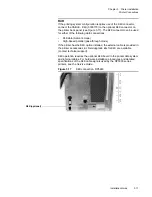
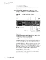
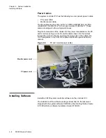
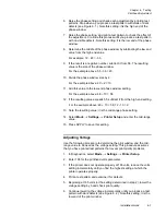
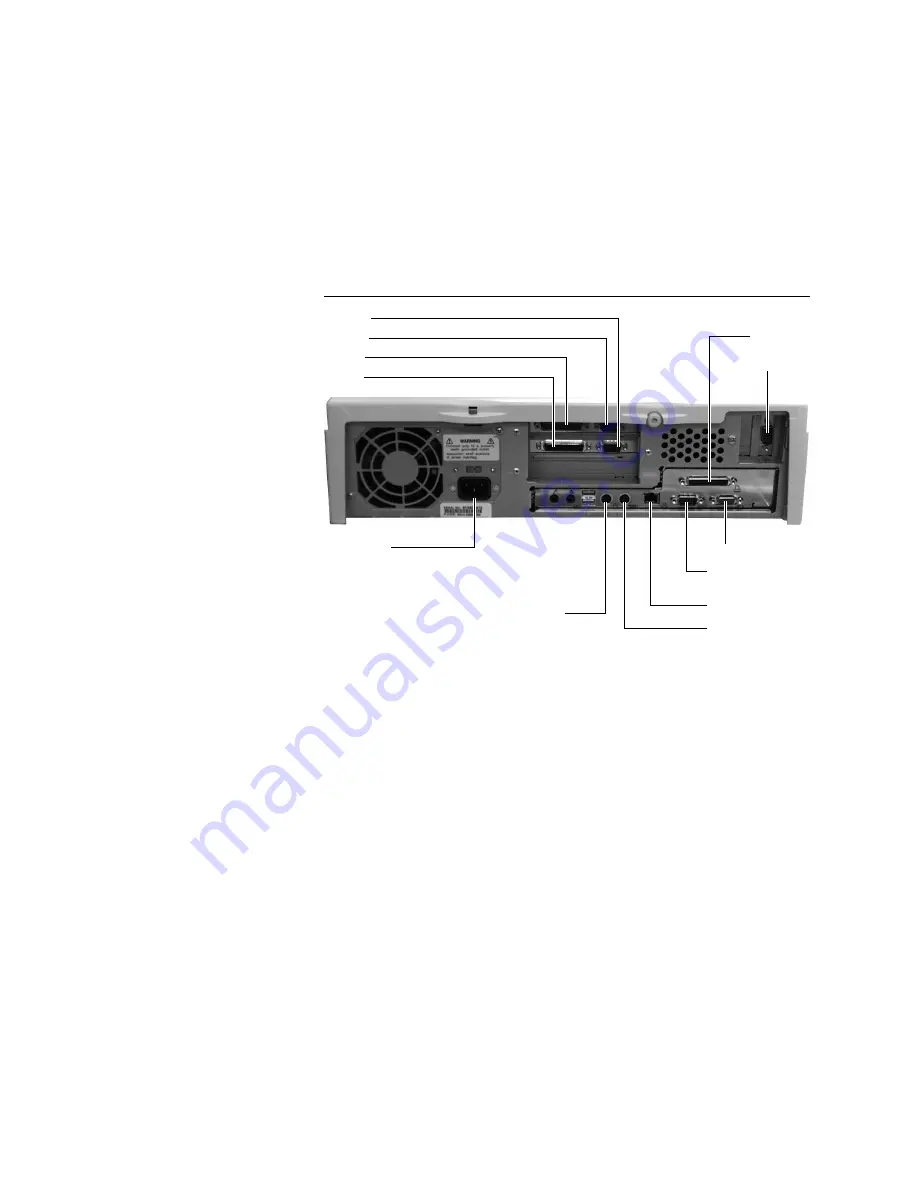
Figure 4.6 shows all the system controller PC connectors. Not all
connectors are used.
Note: The tach and cue connection to the PC is described in “Cabinet
Connections” because it connects the system enclosure to another
printing system component.
Figure 4.6
Controller PC connectors, back panel
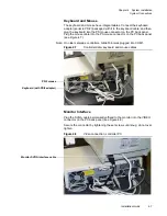
Data Cable
The data cable is connected between the controller PC and the printer.
The data cable can be any of the following types:
•
CENTRONICS (parallel) and RS 232 (serial)
•
K4K
Connect the RS 232 (serial) cable (0178552 or 0139601) to a COM port
on the PC. COM2 is the standard configuration, but another port can be
used. The correct COM port must be configured in Jetscape or CS150.
Connect the CENTRONICS (parallel) cable (0178550) to an LPT port on
the PC. The other end goes to the CENTRONICS connector on the
printer connector panel. LPT1 is the standard configuration, but another
port can be used. The correct LPT port must be configured in Jetscape or
CS150. The CS150 dongle is already connected to LPT1 on a CS150 or
dual controller (see the controller software
Installation Guide
).
Connect the K4K cable to an LPT port on the PC. The correct LPT port
must be configured in Jetscape or CS150.
For a multi-printer system, see the Multi-Printer Interface
Installation
Instructions
for a connection diagram.
PC power
LPT3
LPT1
COM3
COM4
COM2
LPT2
Video
Serial mouse
Network port
(COM1)
PS2 mouse
PS2 keyboard
Summary of Contents for VERSAMARK DP5120
Page 1: ...Versamark DP5000 Series Printers DP5120 DP5122 and DP5240 Installation Guide ...
Page 2: ......
Page 3: ...Versamark DP5000 Series Printers DP5120 DP5240 and DP5122 Installation Guide ...
Page 8: ......
Page 12: ...Contents Figures 4 DP5000 Series Printers ...
Page 14: ...Contents Tables 4 DP5000 Series Printers ...
Page 32: ...2 16 DP5000 Series Printers Chapter 2 Unpacking Printheads ...
Page 52: ...3 20 DP5000 Series Printers Chapter 3 Printer Installation Printer Connections ...
Page 76: ...B 2 DP5000 Series Printers Appendix B Tach and Cue Wiring ...
Page 80: ...C 4 DP5000 Series Printers Appendix C Site Requirements Space Requirements ...
Page 81: ......


