3-10
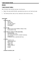
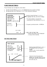
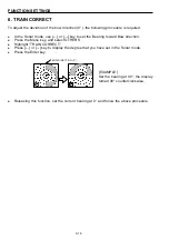
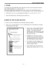
FUNCTION SETTINGS
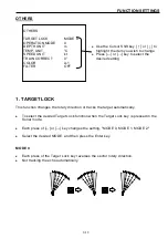
DISPLAY ITEM SELECTION
DISP ITEM SEL.
STEP (SONAR)
10°
STEP (BOTTOM SCAN)
5°
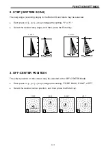
OFF-CENTER POS.
FORE
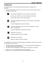
Use the Cursor Shift key [
↑
] or [
↓
] to
highlight the item you wish to change.
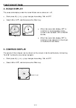
SCALE DOTS
ON
COMPASS DISP.
OFF
Press [
←
] or [
→
] key to select the
desired setting.
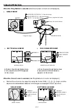
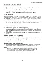
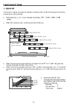
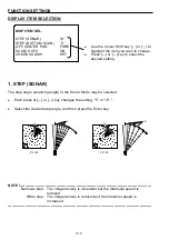
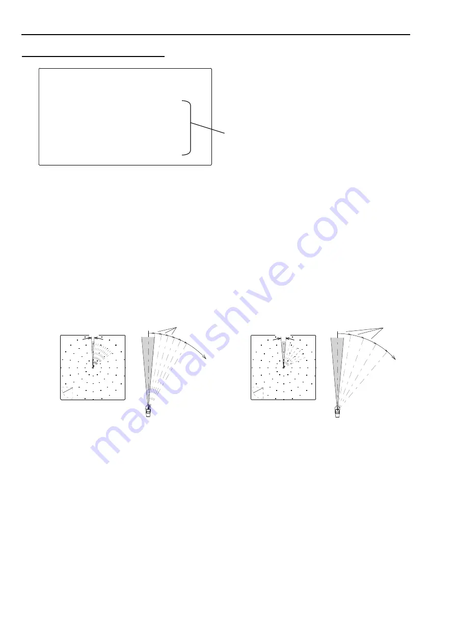
1. STEP (SONAR)
The step angle (scanning angle) in the Sonar Mode may be selected.
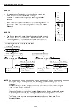
Each press of [
←
] or [
→
] key changes the setting, "5° or 10°."
Select the desired step angle, and then press the Enter key.
5°STEP 10°STEP
NOTE !---------------------------------------------------------------------------------------------------------
Narrower step:
The image density is increased but the rotational speed is
reduced.
Wider step: The image density is reduced but the rotational speed is
increased.
----------------------------------------------------------------------------------------------------------------------
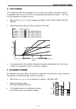
5゜
5゚
10゜
10゚
Summary of Contents for ESR-S1BB
Page 1: ......
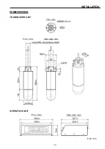
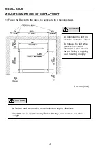
Page 56: ...4 3 INSTALLATION DIMENSIONS TRANSDUCER UNIT Unit mm OPERATION UNIT...
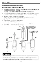
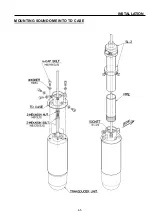
Page 58: ...4 5 INSTALLATION MOUNTING SOUNDOME INTO TD CASE...
Page 73: ......


