


6
Function settings………………………………………………………………………
3 - 5
Setting Functions
Gain Up……………………………………..
TVG Curve…………………….…..………..
3 - 5
3 - 6
3 - 7
Dynamic Range……………….….………..
3 - 7
Pulse Width………………….…….………..
3 - 8
TX Power……………………….…….……..
3 - 8
Reduction
Interference Reduction……..……………..
Noise Reduction…….………………….….
3 - 9
3 - 9
3 - 9
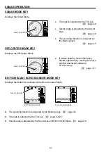
Display Item Selection
Step (Sonar)…………….…………….…….
3 - 10
3 - 10
Step (Bottom Scan)…..……………………
3 - 11
Off-Center Position...………………..…….
3 - 11
Scale Display…………………………..…...
3 - 12
Compass Display……………………..……
3 - 12
Others
Target Lock………………………….……...
3 - 13
3 - 13
Operation Mode……………………….…...
3 - 15
Depth Unit…………………………….…….
3 - 15
Temperature Unit…………………….…….
3 - 15
Speed Unit…………………………….…….
3 - 15
Train Correct………………………….…….
3 - 16
Color…………………………………………
Filter…………………………………………
3 - 17
3 - 18
Chapter 4 INSTALLATION
…………………………………………………………….
4 - 1
Installation
Position……………………………………………..………….
4 - 2
Dimensions………………………………………….………………………
4 - 3
Transducer
Unit
Installation
4 - 4
Mounting Joint Pipe into Soundome…..…………………………….
4 - 4
Mounting Soundome into TD Case...………………………………..
4 - 5
Mounting Method of Display Unit…………………………………………
4 - 6
Connections.………………………………………………………………...
4 - 7
Wiring among Units.……………………………………………………….
4 - 7
Electrical Connections - Terminals………………………..………..…….
4 - 8
Chapter 5 OPTION
…………………………..……………………………………......
5 - 1
Option……………………………………………..…………………………
5 - 2
Chapter 6 APPENDIX
…………………………..…………………………………......
6 - 1
Daily Maintenance…………………………….….………………………..
6 - 2
Disposal………………………………………………..……………………
6 - 3
Specifications…………………………………….…………………………
6 - 4
Remote Controller……………………………………………..……………
6 - 5
Memo of Operation Mode…………………………………………………
6 - 7
Summary of Contents for ESR-S1BB
Page 1: ......
Page 56: ...4 3 INSTALLATION DIMENSIONS TRANSDUCER UNIT Unit mm OPERATION UNIT...
Page 58: ...4 5 INSTALLATION MOUNTING SOUNDOME INTO TD CASE...
Page 73: ......


