Chapter 4
KGC-1
Installation
Operation
Manual
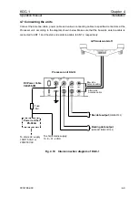
4.7.1 Connectors pinouts of on the Processor unit
DATA1
ANT
1
ANT
2
DATA3
DATA2
POWER
GND
ON
DATA
ALARM
POWER
DATA4
MODE
OFF
①
Ground (GND)
②
Serial (TX+)
③
Serial output -(TX-)
④
Serial input + (RX+)
⑤
Serial input -(RX-)
⑥
NC
NMEA / IEC61162 IN/OUT
②
①
③
④
⑤
⑥
DATA1 ~ 3
Locations of connectors on the Processor unit
DC
入力(
10.8 ~ 31.2VDC
)
①
DC+
③
①
②
②
DC-
③
NC
POWER
①
Ground (GND)
②
Serial
(
TX+
)
③
Serial output- (TX-)
④
Serial input + (RX+)
⑤
Serial input a-(RX-)
⑥
+12V (+12V)
NMEA / IEC61162 IN/OUT
②
①
③
④
⑤
⑥
DATA4
Fig. 4.11 Connector pinouts at the Processor unit
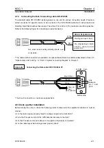
4.7.2 Connecting the DC cable CW-255-2M to DC mains supply
White
Black
DC+
DC-
To Processor unit
4-10
93121652-00

