KGC-1
Chapter
4
Operation Manual
Installation
93121652-00
4-11
4.7.3
Connecting the Data Connecting cable CW-376-5M
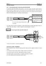
The standard cable CW-376-5M has flying leads on one end for various connection needs. Prepare a
suited connector for specific device to be connected. The CW-376-5M cable has 6 active leads and
shielding braid that sheathes these leads. The white (TX+) and red (TX-) leads are used for signal line.
Refer to the following figure for connecting an external device.
* The cables with connectors are available on optional basis. Select a suitable cable listed in Para. 2.5
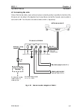
“Optional items list” and Fig. 1.2 “KGC-1 System connecting diagram” in Chapter 1.
Appendix
Connecting the Data cable CW-376-5M to PC
Rx+(Signal input +/Hot)
Rx- (Signal input -/Cold)
White
Red
D-SUB
9 pin
Solder side
Link
between
pin 7 and
pin 8
White
Blue & Black
Green &
Red
Orange
No connection
1
CAUTION
:
This line must not be
grounded GND.
Radar or Navigation device
Non active leads including shielding sheath must
be insulated.
5
* The D-sub connector is a customer-supplied item.
4.8 Check up after installation
Before turning the unit on, check the following points to make sure the equipment functions in normal
manner.
(1) Is the mains supply properly rated for voltage range and current drain?
(2) Are the Processor unit and the GPS antenna securely connected?
(3) Is the Processor unit and radar set or navigator unit properly connected?
(4) Is the cable layout well arranged and properly done?

