background image

KGP-925 


    Chapter 8 Setup Procedure     

0093192502-01 


   8-9   

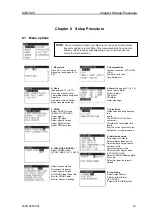
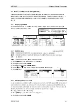
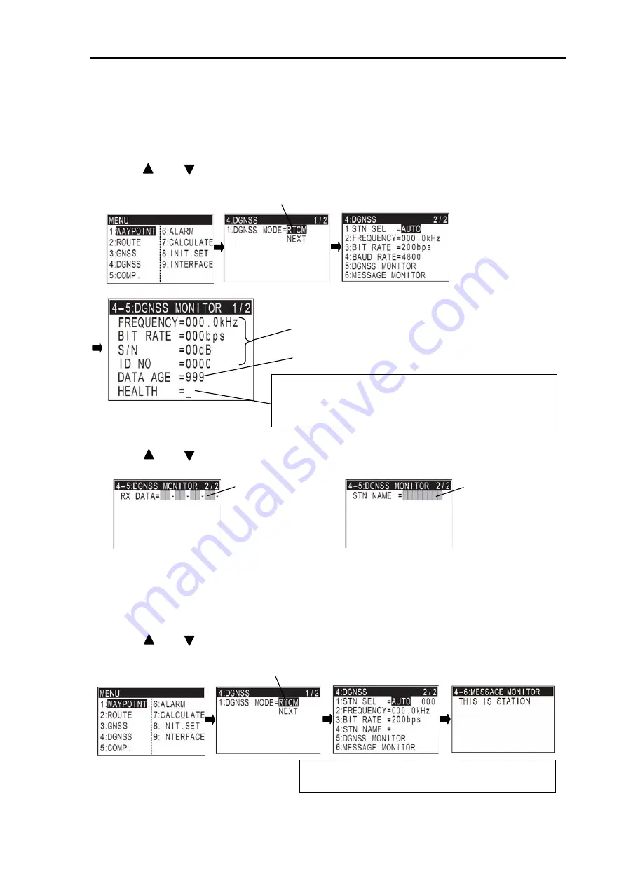
8.3.6  DGNSS monitor  

DGNSS monitor provides information on the DGPS beacon receiver interface and receiving status. 

(1) Press [

MENU

] key until Menu options 1 to 9 appears.


(2) Press [

4

] key to select “

4: DGNSS

”. 

(3) Press [        ] or [        ] key to move cursor onto “

NEXT

” and 2/2 page is displayed. 

(4) Press [

5

] key to select “

5: DGNSS MONITOR

”. 


(5) Press [        ] or [        ] key to change pages of DGNSS monitor. 


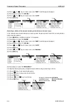
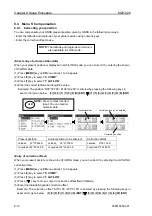
8.3.7  Message monitor 


Message monitor provides DGPS text message. 

(1) Press [

MENU

] key until Menu options 1 to 9 appears.


(2) Press [

4

] key to select “

4: DGNSS

”. 

(3) Press [        ] or [        ] key to move cursor onto “

NEXT

” and 2/2 page is displayed. 

(4) Press [

6

] key to select “

6: MESSAGE MONITOR

”. 


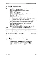
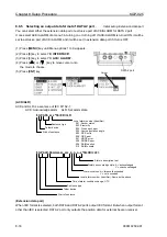
Displays Frequency being received, bit rate, 
S/N ratio and ID No (beacon station number)


Display age of DGNSS data 

HEALTH 

indicates health status of reference station. 

is best. Reliability degrades as the number increases up to 

5

indicates reference station not monitored. 

means reference station not working.


Cursor 

Cursor 

NOTE: It is only on the condition that message type 

16 is broadcasted

Data from beacon 
receiver is displayed

Station name is 
displayed 

Internal beacon receiver type 

External beacon receiver type 

Summary of Contents for KGP-925

Page 1: ......

Page 2: ...ied and the rest of the sheets are not changed The document number is shown in the footer area right or left bottom of each sheet c 2011 2012 Koden Electronics Co Ltd All rights reserved No part of this publication may be reproduced transmitted translated in any form by any means without the written permission of Koden Electronics Co Ltd The technical descriptions contained in this publication are...

Page 3: ...the unit after long periods of use Allergies can result from the inhalation of this dust therefore during inspection and cleaning it is advisable to use a mask Static Electricity Static sensitive semiconductor devices are used in this unit Before changing the printed boards be careful not to damage any of these devices due to electrostatic build up from carpet clothes seats etc Liquid Crystal Disp...

Page 4: ... Warning High Voltage mark Prohibition mark To handle the equipment ignoring this sign may lead to injury to the human body or damage to the equipment Alarm To handle the equipment ignoring this sign may lead to electrical shock to the human body This sign indicates that a specified action is prohibited The prohibited action will be shown in the vicinity of the mark To handle the equipment ignorin...

Page 5: ...Information About GPS and GLONASS Outline of the equipment Equipment composition Software type name Corresponding with Technical Regulations Chapter 2 Equipment Composition Standard equipment list Optional items list Chapter 3 Specification GPS GLONASS receiver section Display section Data Input Output Power requirements Compass safe distance Environmental conditions External dimensions and weight...

Page 6: ...ypoint LAT LONG data Setup of waypoint navigation Cross track error and course deviation angle Storing and erasing routes Route setup Setting an anchor position Track display Chapter 7 Alarms Kinds of alarms Alarm explanation Setting and canceling Chapter 8 Setup Procedure Menu options Menu 3 GNSS Menu 4 Differential GNSS DGNSS Menu 5 Compensation Menu 8 Initial setting Menu 9 Interface Initializa...

Page 7: ...odic inspection and cleaning Troubleshooting Chapter 11 Technical Reference Digital interface IEC 61162 1 Ed 4 Chapter 12 Communication with external navigation system Changing to the EXTERNAL mode Route data transfer Annex Menu Tree DGNSS beacon reference stations list Decca zone ...

Page 8: ...formation Page No 1 1 About GPS and GLONASS 1 1 1 1 1 General 1 1 1 1 2 Positioning by GPS GLONASS 1 1 1 1 3 Time required for position fix 1 1 1 2 Outline of the equipment 1 2 1 3 Equipment composition 1 2 1 4 Software type name 1 2 1 5 Corresponding with Technical Regulations 1 4 ...

Page 9: ...ing your position latitude longitude and height is determined at the intersection point of four spheres formed by four satellites 1 1 3 Time required for position fix In the following circumstances your GPS GLONASS receiver takes more time to fix position 1 When you turned the GPS GLONASS receiver for the first time 2 The stored orbital data is not suitable for the available satellite or purged du...

Page 10: ... 73 and IEC technical standards shown below IEC 60945 4th Edition 2002 08 General IEC 61108 1 Ed 2 0 2003 07 Ship borne GPS Receiver IEC 61108 2 Ed 1 0 1998 06 Ship borne GLONASS Receiver IEC 61162 1 Ed 4 0 2010 11 Digital Interface 1 3 Equipment composition The equipment composition of KGP 925 is shown in Figure 1 1 1 4 Software type name The following software type is used in KGP 925 GPS GLONASS...

Page 11: ...otter sounder CVG 80 200 Echo sounder CVS 841series CVS 842 852series Marine radar MDC 900series MDC 1800series MDC 2000series MDC 2200series MDC 2500series MDC 2900series Marine radar MDC 700series MDC 1000series MDC 1500series MDL 1100series Chart plotter Marine radar Echo sounder Auto pilot AIS Other brand Echo sounder CVS 126 128series AIS transceiver KAT 100 Standard configuration Option Prep...

Page 12: ...GP 925 has an appropriate marking The marking can be performed by one of four variants depending on surface color of equipment The marking of navigation should be done by the manufacturer supplier and should be applied right to device surface 1 5 4 Shipborne combined GPS GLONASS Receiver Equipment type KGP 925 has marking by caution plates in Russian and English HIGH VOLTAGE 1 5 5 Shipborne combin...

Page 13: ...nes for recycling 1 Shutting off the equipment from power supply source pulling out of accumulator batteries 2 Disassembling of the equipment by hand extracting dangerous elements and material suitable for repulping unsoldering of radioelements precious metals disassembling of plastic parts and etc 3 Separating of elements by hazard class and material type 4 Delivering of separated elements for re...

Page 14: ...KGP 925 Chapter 2 Equipment Composition 0093192502 00 Contents Chapter 2 Equipment Composition Page No 2 1 Standard equipment list 2 1 2 2 Option items list 2 1 ...

Page 15: ...3 5M 6 pin water resistant connectors both ends 5m 02 CW 376 5M A 6 pin water resistant connector and other end plain 5m 03 Connecting cable CW 391 1 5M A 8 pin water resistant connector and other end plain w EMI core 5m 04 Junction box JB 10 1 input 3 outputs X 2 circuits 0 4kg 05 Power rectifier PS 010 With 5A fuses 2pcs 3 5kg 06 AC power cable VV 2D8 3M For PS 010 both ends plain 3m 07 Flush mo...

Page 16: ... No 3 1 GPS GLONASS receiver section 3 1 3 2 Beacon receiver section Internal beacon receiver type only 3 1 3 3 Display section 3 1 3 4 Data Input Output 3 2 3 5 Power requirements 3 2 3 6 Compass safe distance 3 2 3 7 Environmental conditions 3 2 3 8 External dimensions and weight 3 3 ...

Page 17: ... in latitude Plotting interval 10 20 30 seconds 1 3 5 minutes 0 1 0 5 1 nm sm km Track display Plotting capacity 2 000 points Position data display Latitude longitude in increments of 0 0001 minute converted Loran C LOPs converted Loran A LOPs converted Decca LOPs Navigational display Speed course velocity made good course made good elapsed time altitude distance bearing cross track error course d...

Page 18: ...Power consumption Less than 4 0 W at 24VDC Less than 4 5 W at 24VDC Internal beacon receiver type AC Operation AC DC rectifier PS 010 is required Input voltage range 115 VAC or 230 VAC 3 6 Compass safe distance Standard 0 8m Steering 0 4m 3 7 Environmental conditions 1 Temperature and humidity Display unit 15 to 55 C Operating temperature Antenna unit 40 to 85 C Humidity 93 40 C 2 Vibration The eq...

Page 19: ...iver type Refer to Figure 3 1 for the exterior with dimensions Refer to Figure 3 2 for service space required Refer to Figure 3 3 for exterior of antenna unit with dimensions Refer to Figure 3 4 for exterior of beacon antenna coupler with dimensions Internal beacon receiver type only Figure 3 1 The Exterior of KGP 925 with dimensions Figure 3 2 Service space required for KGP 925 Unit mm inch Unit ...

Page 20: ...2 01 Unit mm inch Figure 3 3 The Exterior of antenna unit with dimensions MA 620G with cable 10m Weight Without cable 0 18kg Figure 3 4 The Exterior of beacon antenna coupler with dimensions Option Weight Without cable 0 4kg BA 02L K with cable 15m ...

Page 21: ...le mounting 4 1 4 5 2 Flush mounting 4 3 4 6 Antenna unit installation 4 4 4 6 1 Selecting the best site of GPS GLONASS and beacon antenna units 4 4 4 6 2 Fixing the GPS GLONASS antenna unit 4 5 4 6 3 Fixing the beacon antenna coupler and receiving antenna internal beacon receiver type only 4 5 4 7 Cable connections to KGP 925 4 6 4 7 1 Single connection 4 6 4 7 2 Multi connections 4 7 4 8 Connect...

Page 22: ...he units To achieve best operational performance the following factors must be considered 1 The display unit should be positioned in the location where the external situation can be viewed 2 Locate the display so that it provides easy viewing from all likely operator s positions 3 Select a position safe and free from dampness water spray rain and direct sunlight 4 Provide enough space for servicin...

Page 23: ...Chapter 4 Installation KGP 925 4 2 0093192502 01 Figure 4 1 Fitting detail of KGP 925 in table mounting mode Figure 4 2 Service space required for KGP 925 Unit mm inch ...

Page 24: ... unit onto the mounting bracket 3 Put the display on the flush mount and fix with two 2 slotted head screws 4 Put the display on the opening and fix with four 4 tapping screws In case you use M4 screws to fix the display select an appropriate screw length that best suits fixing the unit to the panel thickness Figure 4 3 Fitting KGP 925 in flush mounting mode Unit mm inch ...

Page 25: ...d L type TX antenna 4 At least 1 meter 3 3 feet away from the receiving antenna 5 Outside radar transmitting beam 30 to 40 6 At least 1 meter 3 3 feet away from the radar antenna 7 At least 5 meters 16 5 feet away from the Inmarsat antenna 8 At least 3 meters 9 8 feet away from the loop antenna 9 At least 0 5 meters 1 6 feet above the large metal surface Figure 4 4 Recommended Antenna MA 620G BA 0...

Page 26: ...xing the beacon antenna coupler and receiving antenna Internal beacon receiver type only Case1 Case2 Antenna unit MA 620G Antenna extension pole not supplied Screw 1 14UNS 2B Antenna unit MA 620G FB1 Base mounting Roof top Case2 Case1 BA 03 RA 14 Option BA 03 RA 14 Option RA 14 is a name in the KODEN ...

Page 27: ...W 373 5M CW 373 5M CW 373 5M CW 376 5M Chart plotter Marine radar Echo sounder Auto pilot AIS Other brand Chart plotter GTD 110 150 Plotter sounder CVG 80 200 Marine radar MDC 900series MDC 2000series MDC 2200series MDC 2500series MDC 2900series Chart plotter Marine radar Echo sounder Auto pilot AIS Other brand CW 376 5M Echo sounder CVS 1410series CVS FX series Use the cable Attached to CVS Echo ...

Page 28: ... Chart plotter GTD 110 150 Plotter sounder CVG 80 200 Marine radar MDC 900series MDC 2000series MDC 2200series MDC 2500series MDC 2900series Chart plotter Marine radar Echo sounder Auto pilot AIS Other brand Standard configuration Option Prepared by a customer Legend CW 376 5M Junction Box JB 10 Customer s supply CW 376 5M Echo sounder CVS 1410series CVS FX series Use the cable Attached to CVS Ech...

Page 29: ...6 15V DATA 1 5 6 2 3 4 DATA 2 1 GND SHIELD 2 TXD 3 TXD 4 RXD 5 RXD 6 BUZZER STP 7 BUZZER STP 8 EXT BUZZER 1 5 6 2 3 4 7 8 POWER 1 DC 2 F GND 3 DC 1 3 2 General data output RXD is used only maintenance External beacon receiver Extension data output External buzzer 2 ACK ALARM OUT 3 ACK ALARM OUT When ACK ALARM Mode is ON See page 8 19 To display unit Blue White Red Orange Black Green GND TXD TXD RX...

Page 30: ...s RS 422 When CW 398 is used This port is an only for external alarm system ACK ALARM output signal level is RS 422 and EXT BUZZER out put can drive a relay 24V 10mA BUZZER STP is an input port for stopping a buzzer and impresses 24V 4 9 Inspection after installation Before you turn the unit on check the following points to make sure the system operates properly 1 Is the ship s supply voltage and ...

Page 31: ...ontrast and brightness 5 2 5 4 Selecting the screen 5 3 5 4 1 A NAV1 screen 5 3 5 4 2 B NAV2 screen 5 4 5 4 3 C NAV3 screen 5 5 5 4 4 D PLOT screen 5 5 5 5 Storing present position EVENT 5 7 5 5 1 AUTO 5 7 5 5 2 MANUAL 5 7 5 5 3 Changing the event symbols 5 7 5 6 Using MOB Man over board key 5 8 5 7 Recalling event or MOB position 5 9 5 8 Displaying average speed average bearing and elapsed time 5...

Page 32: ...own Stores event positions Recalls memory position entry of numerical values and selection North or South latitude or East or West longitude Turns the power on and changes the brightness of control panel 5 levels Enters a numeric optional parameter Turns the power off Recalls the menu Cursor shift Left Changes display contrast in 8 levels Clears numeric optional parameter or stops alarm sound temp...

Page 33: ... turn NAVIGATOR off All data before power off is kept in memory for later use PWR DIM Press to change the LCD brightness in 5 levels CTRS Press to change the LCD contrast in 8 levels Blinks when NAVIGATOR is searching GPS satellites Blinking When NAVIGATOR receives signals from 3 or more satellites it displays present latitude and longitude position with solid N or S and W or E No blinking NOTE Th...

Page 34: ...aypoint and memory position 5 4 1 A NAV1 screen Standard Text mode Page 1 Page 2 NOTE Each following is each screen in the state where waypoint routes and anchor watch are not set up A screen when they are set up is mentioned later Current date mm dd yy Present time Blank Universal time L Local time Position Speed Course Antenna height Blinks when your position has failed to fix RAIM status Screen...

Page 35: ... position LAT LONG is displayed when displaying position data in Loran C Loran A or Decca LOPs mode Loran C Loran A or Decca LOPs is displayed when displaying position data in LAT LONG mode Present time Speed Course Blinks when your position has failed to fix NOTE The navigation graph shows your boat position and the relative bearing Page number Course Speed Position Blinks when your position has ...

Page 36: ...has failed to fix Your boat NAV3 screen shows a 3 dimensional view indicating the distance course cross track error and deviation from the waypoint The boat icon does not move in OFF mode Distance and bearing from your present position to cross cursor position Cross cursor position Cross cursor Page number Course Speed Position Blinks when your position has failed to fix Scale Your boat position T...

Page 37: ...Chapter 5 Basic Operation KGP 925 5 6 0093192502 00 Page 4 Close up of PLOT screen ...

Page 38: ...s 1 Press MODE key until D PLOT screen appears 2 Press SEL key until page 6 screen appears 3 Press or key and move cursor onto the SYMBOL 4 Press ENT key to display symbol list 5 Press or key and move cursor onto the new symbol 6 Press ENT key to select new symbol CAUTION EVT key does not function when positioning is invalid EVT 001 15 04 59 35 38 180N 139 42 990E The latest event number Storage d...

Page 39: ...your position is stored immediately and MOB screen appears You can see the distance and bearing from your present position to the point you pressed MOB key Proximity alarm blinking Alarm sounds when you approached 0 1 nm from the point you pressed MOB key Distance in nm from your present position to the point you pressed MOB key Bearing to the point where you pressed MOB key Point where you presse...

Page 40: ...ss after you pressed MOB key NOTE The time display that is shown when the elapsed time has exceeded 99 minutes 59 seconds after the MOB key was pressed Speed in knots Course Present position NOTE You can use only the following five keys in MOB mode EVT CLR CTRS PWR OFF CLR Clears the MOB mode and returns to the previous screen when you pressed MOB key When alarm is sounding press CLR key to stop i...

Page 41: ... elapsed time Course made good A true bearing from origin to present position Elapsed time The time elapsed after your power on or after you have pressed the CLR Reset key NOTE This function is also available even when the waypoint navigation root navigation or anchor position is in operation Velocity made good Example 15 0 knots Course made good Example 152 1 Elapsed time Example 05 hours 59 min ...

Page 42: ...igation 6 6 6 2 7 D PLOT screen during waypoint navigation 6 6 6 3 Cross track error and course deviation angle 6 7 6 3 1 Navigation graph of NAV2 screen 6 7 6 3 2 Electronic fairway NAV3 screen 6 8 6 4 Storing and erasing routes 6 10 6 4 1 Storing your route 6 10 6 4 2 Automatic switching of waypoints 6 11 6 4 3 Erasing point data 6 11 6 4 4 Erasing a single route 6 12 6 5 Route setup 6 13 6 5 1 ...

Page 43: ...creen 6 19 6 6 4 Reentering an anchor position 6 19 6 6 5 Canceling anchor position 6 19 6 6 6 B NAV2 screen during anchor position setup 6 20 6 6 7 C NAV3 screen during anchor position setup 6 20 6 6 8 D PLOT screen during anchor position setup 6 20 6 7 Track display 6 21 6 7 1 Display a cross cursor on PLOT screen 6 21 6 7 2 Screen scrolling 6 21 6 7 3 Scaling the PLOT screen 6 22 6 7 4 Changing...

Page 44: ...w 3 5 3 8 1 8 0 N 1 3 9 4 2 9 9 0 E 6 1 2 Writing comment Try to use comments for often used positions Nine symbols are available If you set a symbol at the beginning of your comment the symbol is shown at waypoint If not an asterisk and waypoint number are shown on PLOT screen 1 Press MENU key until Menu options 1 to 9 appears 2 Press 1 key to select 1 WAYPOINT 3 Enter storage number 200 to 399 u...

Page 45: ...eric keys The coordinates will appears 5 Press ENT key to enter the source point number 6 Enter a destination point number 200 to 399 using numeric keys The coordinates will appears Use another number if you do not wish to erase the existing number data 7 Press ENT key to copy the storage data A comment if any is also copied Example of symbols Reference point Fishing spot Shallow Sunken ships Buoy...

Page 46: ... enter up to 10 letters by repeating 6 and 7 steps 9 Press ENT key and decide of a comment 6 1 5 Erasing a single waypoint 1 Press MENU key until Menu options 1 to 9 appears 2 Press 1 key to select 1 WAYPOINT 3 Enter storage number 001 to 399 using numeric keys 4 Press ENT key The storage number data will appears 5 Press CLR key A confirmation message will appears 6 If OK press ENT key to erase th...

Page 47: ...n the new waypoint is selected the waypoint navigation to it will commence and the specified position along with the comment QUICK will be assigned to the position number 398 Old data is replaced with a new during quick WPT setup While the 1st to 4th pages of either the A NAV 1 B NAV 2 C NAV 3 or D PLOT are displayed 1 Press 0 key to display QUICK pop up menu 2 Enter latitude and longitude For exa...

Page 48: ... PLOT screen appears 2 Press SEL key until page 5 screen appears 3 Press key to move cursor to the RESET letters 4 Press ENT key to cancel WPT setting 6 2 5 B NAV2 screen during waypoint navigation ON letters are displayed and number are cleared Time to go from present position from WPT WPT position Page number Arrival time mm dd hh mm Distance from present position from WPT WPT position Page numb...

Page 49: ...meters shown in the 1st 3rd and 4th pages of the D PLOT screen refer to D PLOT screen in OFF mode in page 5 5 and 5 6 They are used in the same manner SEL Distance from present position from WPT WPT position Page number Bearing from present position from WPT Time to go from present position from WPT WPT position Page number Arrival time mm dd hh mm Cross track error WPT position Deviation angle Pa...

Page 50: ...e Waypoint Course deviation angle Cross track error Steer to the left to get back to the original course Bearing to WPT Distance from present Position to WPT True north Origin Course Steering direction Steer to the right to get back to the original course NOTES 1 The cross track error XTE indication is 9 99 nm sm km maximum and doesn t change beyond that limit 2 The XTE bar graph responds up to 1 ...

Page 51: ...e screen When you have sailed 2 nm sm km the present position indication moves toward you and the next 4 nm sm km are shown At point E You are sailing outside of course width Present position This marking moves at the course edge Course line length on the screen At point B At point A Present position Present position At point D At point C Present position Present position Waypoint Distance to WPT ...

Page 52: ...1 nm sm km 2 nm sm km and 4 nm sm km The WPT indication changes when the length exceeds 4 nm sm km At point J You have reached the waypoint At point I You are 0 5 nm sm km away from waypoint Waypoint Present position At point H You are 1 nm sm km away from waypoint The WPT marking moves toward you The WPT marking moves to the center of course line Waypoint Present position The course length closin...

Page 53: ... 4 Enter a route number 01 to 20 using numeric keys 5 Press ENT key to store the route number 6 Press key to move cursor to the forward or backward route setup column 7 Press SEL key to select the forward or backward route navigation 8 Press key to move cursor to the waypoint number column 9 Enter a waypoint number 200 to 399 of the route using numeric keys You can check its memory data on the scr...

Page 54: ...lect 1 ROUTE EDIT Route Input screen is displayed 4 Enter a route number 01 to 20 using numeric keys 5 Press key to move cursor to the waypoint number you wish to erase Its data and comment if any are displayed 6 Press CLR key A confirmation message appears 7 If OK press ENT key to erase all points of this route If cancel erasing press CLR key CIRCLE mode Proximity Alarm circle Waypoint Course lin...

Page 55: ...displayed 4 Enter a route number 01 to 20 using numeric keys 5 Press ENT key to recall the route number 6 Press CLR key A confirmation message appears 7 If OK press ENT key to erase all points of this route If cancel erasing press CLR key NOTE To erase all stored data from memory see Erasing entire data from memory page 8 19 Route 01 data has been erased Confirmation message before Erasing route 0...

Page 56: ...h waypoint Use the following steps to start route navigation Select the reverse navigation only after you have reached the final destination or the route navigation may not work properly 1 Press MODE key until A NAV1 B NAV2 C NAV3 or D PLOT screen appears 2 Press SEL key until page 5 screen appears 3 Press or key to move cursor to ROUTE letters 4 Press ENT key 5 Enter a route number 01 to 20 using...

Page 57: ...MODE key until A NAV1 B NAV2 C NAV3 or D PLOT screen appears 2 Press SEL key until page 5 screen appears 3 Press or key to move cursor to ROUTE letters 4 Press ENT key 5 Enter a route number 01 to 20 using numeric keys 6 Press key 7 Enter the new route start point number using numeric keys 8 Press ENT key 6 5 5 Canceling route navigation To cancel waypoint navigation turn ROUTE to OFF on A NAV1 B ...

Page 58: ...2 Press SEL key until page 2 screen appears 3 Press key to display RNG 4 Press key to display TRNG 1 Press MODE key until B NAV2 C NAV3 or D PLOT screen appears 2 Press SEL key until page 4 screen appears 3 Press key to display TTG 4 Press key to display T TTG NOTE RNG shows the distance to the next waypoint TRNG shows the total distance to the final destination TTG shows the time to the next wayp...

Page 59: ...ble Speed Present position Course Page number Range Radius of navigation graph Cross track error WPT position Deviation angle Page number Route number 01 Forward or backward navigation Next route point number 001 NOTE To change a display page Press this key SEL NOTE Positioning has failed or the time to go has exceeded 999 hours 59 minutes RNG 9999 ETA 12 31 23 59 Blinks when position fix is unava...

Page 60: ...Route point WPT position Page number Bearing to the next Point Total distance Can also be shown NOTE To change a display page Press this key SEL For description of the parameters shown in the 1st 3rd and 4th pages of the D PLOT screen refer to D PLOT screen in OFF mode in page 5 5 and 5 6 They are used in the same manner ...

Page 61: ...e comment ANCH 1 Press MODE key until B NAV2 C NAV3 or D PLOT screen appears 2 Press SEL key until page 5 screen appears 3 Press or key to move cursor to the letters ANCH 4 Press ENT key Current position is registered and selected as the anchor position 6 6 2 Recalling anchor position You can check the anchor position on any of A NAV1 B NAV2 C NAV3 and D PLOT screens during anchoring 1 Press MODE ...

Page 62: ...letters 6 Press ENT key 6 6 4 Reentering an anchor position You can reenter a new anchor position and start to calculate navigation While the 1st to 4th pages of either the A NAV 1 B NAV 2 C NAV 3 or D PLOT are displayed 1 Press ENT key to set the point as WPT 6 6 5 Canceling anchor position 1 Press MODE key until A NAV1 B NAV2 C NAV3 or D PLOT screen appears 2 Press SEL key until page 5 screen ap...

Page 63: ...mber Arrival time mm dd hh mm Distance from present position to anchor position WPT position Page number Bearing from present position to anchor position Cross track error Anchor position Deviation angle Page number NOTE The 3D PLOT screen shows the distance bearing cross track error XTE and course deviation angle to the waypoint Your boat icon does not move in the ANCH mode NOTE To change a displ...

Page 64: ... press the EVT key to store the cross cursor position Note not the present ship s position 6 7 2 Screen scrolling You can scroll the PLOT screen pages 1 2 3 or 4 in any direction so that your ship is always shown on the screen If your ship moves off the screen it will automatically return to the center of the display D PLOT screen Cross cursor Page number Position LAT LONG of Cross cursor Present ...

Page 65: ...ption is setup Changing the event symbol To change the event symbol place cursor on SYMBOL option and press ENT key Activating event numbers 000 to 199 Turn ON the EVENT option and you can save events the present position marking into memory numbers 000 to 199 Activating event numbers 200 to 399 Turn ON the WAYPOINT option and save events the present position marking into memory numbers 200 to 399...

Page 66: ...NIT RNG of 8 INITIAL Turning tracking off Set the TRACK option to OFF to stop recording the track on PLOT screen Your present position marking moves on the screen Set the TRACK option to ON to record the track on PLOT screen Erasing the track If you press the CLR key when the cursor is positioned at TRACK CLR a confirming message DELETE will appear Press the ENT key to delete every track line curr...

Page 67: ...Chapter 7 Alarms Page No 7 1 Kinds of alarms 7 1 7 1 1 Anchor watch alarm ANCH 7 1 7 1 2 Proximity alarm PROX 7 1 7 1 3 Cross track error alarm XTE 7 2 7 1 4 Course deviation angle alarm CDI 7 2 7 2 Alarm explanation 7 2 7 3 Setting and canceling 7 3 ...

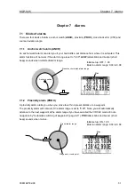
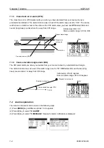
Page 68: ...f alarm range 7 1 2 Proximity alarm PROX A proximity alarm alerts you when you arrive to within a preset distance to a waypoint The proximity alarm will not work if the alarm range is set to 0 00 Note you will automatically advance to the next waypoint at the alarm range if you have selected the CIRCLE mode of route navigation by Automatic switching of waypoints page 6 11 PRX letters blink and buz...

Page 69: ...urse to steer by a predetermined margin The alarm function does not work if the alarm range is set to 00 CDI letters blink and buzzer long beep sounds when I m away from CDI range 7 2 Alarm explanation The reason of an alarm can be seen in the following ways 1 Press MENU key until Menu options 1 to 9 appears 2 Press 6 key to select 6 ALARM 3 Press 5 key to select 5 MESSAGE Reason for alarm notific...

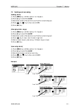
Page 70: ...ess 6 key to select 6 ALARM 3 Select item number of the alarm to be set from the numerical keypad 4 Press key to move cursor to alarm range field 5 Enter an alarm range by numeric key CDI alarm range is 2 digit 6 Press ENT key Canceling alarm 1 Press MENU key until Menu options 1 to 9 appears 2 Press 6 key to select 6 ALARM 3 Select desired alarm number by numeric key 4 Press or key to move cursor...

Page 71: ...3 4 Storing a beacon station Internal beacon receiver type only 8 7 8 3 5 Selecting the DGNSS input signal baud rate External beacon receiver type only 8 8 8 3 6 DGNSS monitor 8 9 8 3 7 Message monitor 8 9 8 4 Menu 5 Compensation 8 10 8 4 1 Correcting your position 8 10 8 4 2 Checking the correction offset 8 11 8 4 3 Disable position correction 8 11 8 4 4 Compensating the compass 8 11 8 4 5 Displa...

Page 72: ...A port 8 16 8 6 3 Explanation of output data sentence 8 17 8 6 4 Selecting an output format of waypoint data 8 17 8 6 5 Selecting an output data format of DATA 2 port 8 18 8 7 Initialization 8 19 8 7 1 Initialization 8 19 8 7 2 Erasing entire data from memory 8 19 8 7 3 Switching between Loran C Lops Loran A LOPs and Decca LOPs 8 19 8 7 4 Changing a storing method for present position EVENT 8 19 8...

Page 73: ...t format Edit the output format IEC 61162 1 Select ACK ALARM output 2 Route See pages 6 13 to 6 17 Store and erase a route Forward backward navigation Selection Automatic route switching Waypoint data switching 4 Diffe GNSS DGNSS Select DGNSS mode RTCM SBAS OFF AUTO Select beacon station Set beacon frequency Select beacon bit rate Set DGNSS input baud rate Monitor DGNSS data Monitor beacon message...

Page 74: ...o 9 appears 2 Press 3 key to select 3 GNSS 3 Press 2 key to select 2 GNSS MODE 4 Press or key to select desired GNSS mode 5 Press ENT key 8 2 3 Selecting a geodetic datum Initial setup WGS 84 The latitude and longitude of GPS system are calculated based on the WGS 84 and GLONASS system is calculated based on the PZ 90 The KGP 925 has been equipped 4 geodetic datum You can select one geodetic datum...

Page 75: ...us positioning You can improve the positioning accuracy by masking the elevation angle However a large mask value shortens the signal receive time and most satellite combinations are rejected 1 Press MENU key until Menu options 1 to 9 appears 2 Press 3 key to select 3 GPS 3 Press 6 key to select 5 ELV MASK 4 Press or key to move cursor onto elevation angle masking 5 Press ENT key 8 2 6 Setting RAI...

Page 76: ...IM ACCURACY 4 Press ENT key 5 Press or key to select desired RAIM accuracy 100m or 10m 6 Press ENT key RAIM accuracy When 100m is chosen it is a long bar display When 10m is chosen it is a short bar display This bar is displayed when a RAIM function is ON It is not displayed at the time of OFF Status 1 SAFE GPS signal is safe to use 2 CAUTION Using a GPS signal necessity or a RAIM function does no...

Page 77: ...rity is RTCM 1 Press MENU key until Menu options 1 to 9 appears 2 Press 4 key to select 4 DGNSS 3 Press 2 key to select 2 DGNSS MODE 4 Press or key to move cursor onto the desired DGNSS mode 5 Press ENT key 8 3 3 Selecting a beacon station Initial setup AUTO A beacon station is selectable in both the manual or auto mode KGP 925 outputs MSK sentence and position data to an external beacon receiver ...

Page 78: ...Press 4 key to select 4 DGNNS 3 Press or key to move cursor onto NEXT and 2 2 page is displayed 4 Press 1 key to select 1 STN SEL 5 Press or key to move cursor onto AUTO 6 Press ENT key 7 Press or key to move cursor onto MANUAL 8 Press ENT key 9 Press 2 key to select 2 FREQUENCY 10 Specify receiving frequency 4 digit of beacon station using numeric keys 0 to 9 11 Press ENT key to set receiving fre...

Page 79: ...erical keys 11 Press ENT key 8 3 4 Storing a beacon station Internal beacon receiver type only When a beacon station is not stored or when change takes place in the data of a beacon station reception from that station is done by registering the station data The user can register up to 20 station numbers in the range of 001 to 020 1 Press MENU key until Menu options 1 to 9 appears 2 Press 4 key to ...

Page 80: ...locating cursor on it or enter a value using numeric keys 21 Press SEL key And one letter or symbol are made to decide 22 You can enter up to 10 letters by repeating 20 and 21 steps 23 Press ENT key and decide of a station name 8 3 5 Selecting the DGNSS input signal baud rate External beacon receiver type only Adjust the baud rate of RTCM SC 104 format signal reception to the output signal baud ra...

Page 81: ...ntil Menu options 1 to 9 appears 2 Press 4 key to select 4 DGNSS 3 Press or key to move cursor onto NEXT and 2 2 page is displayed 4 Press 6 key to select 6 MESSAGE MONITOR Displays Frequency being received bit rate S N ratio and ID No beacon station number Display age of DGNSS data HEALTH indicates health status of reference station 0 is best Reliability degrades as the number increases up to 5 6...

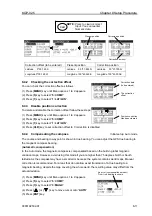
Page 82: ... 3 2 0 0 E ENT Present position Actual position to be entered Correction offset Latitude 35 o 37 893 N Latitude 35 o 37 700 N Latitude 0 o 00 193 N Longitude 139 o 43 348 E Longitude 139 o 43 200 E Longitude 0 o 00 148 W Entry of correction offset When your present position is shown in LAT LONG mode you can correct it by entering the LAT LONG correction data 1 Press MENU key until Menu options 1 t...

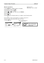
Page 83: ...wn in true bearing You can adjust the GPS true bearing to the magnetic compass bearing Automatic compensation In the Auto mode the magnetic compass is compensated based on the built in global magnetic variation maps However avoid using this mode if you are higher than 75 degrees North or South latitude As the compass may have a small error because the system contains world maps Manual correction i...

Page 84: ...NUAL 5 Press ENT key 6 Press key 7 Press SEL key to change the positive or negative sign of correction offset or 8 Press 0 key to use the current positive or negative sign as it is 9 Enter a 4 digit compensation offset using numeric keys 10 Press ENT key initial setup 0 0 o Setup range 180 0 to 180 0 CLR NOTE Press to clear incorrect Input You can reenter Numeric data An error compensation amount ...

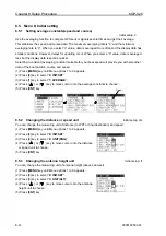
Page 85: ...s 4 key to select 4 TIME 7 Press SEL key to change the positive or negative sign of correction offset or 8 Press 0 key to use the current positive or negative sign as it is 9 Enter a time difference from UTC using numeric keys 10 Press ENT key 11 10 9 8 7 6 5 4 3 2 1 0 1 2 3 4 5 6 7 8 9 10 11 11 10 9 8 7 6 5 4 3 2 1 0 1 2 3 4 5 6 7 8 9 10 11 Figure 8 1 Time difference chart 12 12 12 12 12 12 12 12...

Page 86: ...nd speed 1 Press MENU key until Menu options 1 to 9 appears 2 Press 8 key to select 8 INIT SET 3 Press 1 key to select 1 AVERAGE 4 Press or key to move cursor onto the average constants to choose 5 Press ENT key 8 5 2 Changing the distance or speed unit Initial setup nm You can change the measuring unit of distance to WPT or final destination and speed 1 Press MENU key until Menu options 1 to 9 ap...

Page 87: ... options 1 to 9 appears 2 Press 8 key to select 8 INIT SET 3 Press 5 key to select 5 POSITION 4 Press or key to move cursor onto the LAT LON mode to choose 5 Press ENT key 8 5 6 Changing the latitude and longitudinal display digits Initial setup 001 The following operations enable to display the latitude and longitude of present position up to 0 0001 minute 1 Press MENU key until Menu options 1 to...

Page 88: ...e and set the output cycle in seconds of the IEC 61162 1 output data format 1 Press MENU key until Menu options 1 to 9 appears 2 Press 9 key to select 9 INTERFACE 3 Press 2 key to select 2 IEC EDIT 4 Press key to move cursor onto the sentence to change its cycle 5 Enter an output cycle of selected sentence using numeric keys 6 Press ENT key DATA port Cursor NOTE Set the output cycle for the requir...

Page 89: ... position to waypoint approaching speed to waypoint proximity alarm Recommended Minimum Specific GPS TRANSIT Data UTC time lat long ground speed true bearing magnetic deviation date Route number and waypoint number Max 4 points including next waypoint Route number and waypoint number Max 4 points including next waypoint Loran C Chain Identifier Course Over Ground true and magnetic bearing and Grou...

Page 90: ...IEC 61162 1 ACK Acknowledge alarm ALR Set alarm state Extension data port When IEC format is selected both DATA and DATA 2 ports output IEC format But when output format other than IEC is selected DATA 2 port only outputs the position data for external beacon receiver GP ACK xxx hh CR LF Start of sentence Talker device Sentence type Local alarm number identifier 001 Anchor watch 002 Proximity 003 ...

Page 91: ...ll system parameters again 8 7 2 Erasing entire data from memory You can erase the entire data such as waypoints events MOB and route from memory 8 7 3 Switching between Loran C LOPs Loran A LOPs and Decca LOPs initial setup LORAN C This menu option allows you to select a desired display among the loran C LOP Loran A LOP and Decca LOP 8 7 4 Changing a storing method for present position EVENT init...

Page 92: ...itude west longitude region as the initial value N E N Lat E Long When power is turned on GPS or DGNSS position measurement is started using the north latitude east longitude region as the initial value S W S Lat W Long When power is turned on GPS or DGNSS position measurement is started using the south latitude west longitude region as the initial value S E S Lat E Long When power is turned on GP...

Page 93: ...oints LOPs data 9 4 9 2 1 Storing a new position or updating an existing one 9 4 9 3 Correcting your position LOPs 9 5 9 3 1 Direct entry of actual position data 9 5 9 3 2 Entry of correction offset 9 7 9 3 3 Checking the correction offset 9 9 9 3 4 Disable position correction 9 9 9 4 Calculating LOPs based on LAT LONG data 9 10 9 4 1 Calculating Loran C LOPs based on LAT LONG data 9 10 9 4 2 Calc...

Page 94: ...nts from LAT LONG into Loran C LOPs 1 Press MENU key until Menu options 1 to 9 appears 2 Press 8 key to select 8 INIT SET 3 Press key to move cursor to the letters 7 CHAIN 4 Enter a 4 digit Loran C chain number 5 Enter the highest digit 10 thousand microseconds of two Loran C secondary stations 6 Press ENT key Specifying combinations of secondary stations in Loran A LOPs mode You can convert your ...

Page 95: ...key 5 Press or key to move cursor onto AUTO 6 Press ENT key Manual chain selecting in Decca LOPs mode You can convert both your present position given by GPS and stored position data waypoints and event data from LAT LONG into Decca LOPs 1 Press MENU key until Menu options 1 to 9 appears 2 Press 8 key to select 8 INIT SET 3 Press key to move cursor to the letters 7 CHAIN 4 Press ENT key 5 Press or...

Page 96: ... Following describes the procedure for replacing LAT LONG display with LOP and registering a position in LOP 1 Press MENU key until Menu options 1 to 9 appears 2 Press 8 key to select 8 INIT SET 3 Press 5 key to select 5 POSITION 4 Press or key to select LOP letters 5 Press ENT key Cursor ...

Page 97: ...s of secondary station 2 using numeric keys 10 Press ENT key Loran A LOPs mode 7 Enter a 5 digit data LOPs of secondary station 1 using numeric keys 8 Press ENT key 9 Enter a 5 digit data LOPs of secondary station 2 using numeric keys 10 Press ENT key Decca LOPs mode 7 Enter 2 digit numbers zone lane centilane of secondary station 1 using numeric keys 8 Press ENT key 9 Enter 2 digit numbers zone l...

Page 98: ...2 7 Enter correct 6 digit LOPs of secondary station 2 using numeric keys 8 Press ENT key Present position GPS fix Actual position to be entered Correction offset Secondary st 1 35518 9 μsec Secondary st 1 35520 0 μsec Secondary st 1 0001 1 μsec Secondary st 2 60387 5 μsec Secondary st 2 60386 0 μsec Secondary st 2 0001 5 μsec Correction by Loran A LOPs data entry When your position is displayed in...

Page 99: ...he Decca LOPs correction offset 1 Press MENU key until Menu options 1 to 9 appears 2 Press 5 key to select 5 COMP 3 Press 2 key to select 2 LOP 4 Enter correct Decca LOPs lane and centilane of secondary station 1 using numeric keys 5 Press ENT key 6 Press key to move cursor to Loran A LOPs field of secondary station 2 7 Enter correct Decca LOPs lane and centilane of secondary station 2 using numer...

Page 100: ...ss 0 key to use the current positive or negative sign as it is 10 Enter correction offset 6 digit of secondary station 2 using numeric keys 11 Press ENT key Present position GPS fix Correction offset Actual position to be entered Secondary st 1 35518 9 μsec Secondary st 1 0001 1 μsec Secondary st 1 35520 0 μsec Secondary st 2 60387 5 μsec Secondary st 2 0001 5 μsec Secondary st 2 60386 0 μsec Corr...

Page 101: ...ode you can correct it by entering the Decca LOPs correction offset 1 Press MENU key until Menu options 1 to 9 appears 2 Press 5 key to select 5 COMP 3 Press 2 key to select 2 LOP 4 Press key to move cursor to correction offset field of secondary station 1 5 Press SEL key to change the positive or negative sign of correction offset or Press 0 key to use the current positive or negative sign as it ...

Page 102: ...y until Menu options 1 to 9 appears 2 Press 5 key to select 5 COMP 3 Press 2 key to select 2 LOP 9 3 4 Disable position correction To delete and disable the correction offset follow these steps 1 Press MENU key until Menu options 1 to 9 appears 2 Press 5 key to select 5 COMP 3 Press 1 key to select 1 LAT LON 4 Press CLR key to set correction offset to 0 correction is disabled Correction data to be...

Page 103: ...7 digit latitude using numeric keys 8 Enter N for north or S for south latitude 9 Press ENT key 10 Enter a 8 digit longitude using numeric keys 11 Enter E for east or W for west latitude 12 Press ENT key If you store the calculation result 1 Press key to display page 2 2 2 Enter a data number 200 to 399 using numeric keys The existing data if any is displayed for your checkout 3 Press ENT key Spec...

Page 104: ... field 8 Press ENT key 9 Press or key to select the secondary station 2 10 Press ENT key 11 Press key to move the cursor to latitude field 12 Enter a 7 digit latitude using numeric keys 13 Enter N for north or S for south latitude 14 Press ENT key 15 Enter a 8 digit longitude using numeric keys 16 Enter E for east or W for west latitude 17 Press ENT key If you store the calculation result 1 Press ...

Page 105: ...tations 9 Press ENT key 10 Press key to move the cursor to latitude field 11 Enter a 7 digit latitude using numeric keys 12 Enter N for north or S for south latitude 13 Press ENT key 14 Enter a 8 digit longitude using numeric keys 15 Enter E for east or W for west latitude 16 Press ENT key If you store the calculation result 1 Press key to display page 2 2 2 Enter a data number 200 to 399 using nu...

Page 106: ...1 9 13 Specified data number Data currently stored X L L LOP fixed CAUTION Do not use the converted LOPs position data for waypoint or route navigation because of likely conversion errors Accuracy of converted positions can be off 1 4 mile or more ...

Page 107: ...nts Chapter 10 Maintenance and Troubleshooting Page No 10 1 Periodic inspection and cleaning 10 1 10 1 1 Monthly check 10 1 10 1 2 Maintenance 10 1 10 2 Troubleshooting 10 1 10 2 1 Information required for service 10 1 10 2 2 Troubleshooting 10 1 10 2 3 Error message 10 3 ...

Page 108: ... vessel Satcom number if available 2 Equipment type name 3 Equipment serial number 4 Next port of call ship s agent name fax number email address etc 5 Faulty conditions precisely as possible and the result of on board check 10 2 2 Troubleshooting The following table provides information about first line check schedules to locate a faulty area and gives remedial measure s where applicable Faults d...

Page 109: ...t 1 Is the connection between the display unit and interface cable firmly connected 2 Are the output data format and input data format of external equipment match See page 11 1 1 Reconnect the cable firmly to the display unit 2 Match the data format 10 2 3 Error message An error message may appear when you power on BACKUP ERROR The backup data saved at RAM is faulty ROM CHANGED A checksum differs ...

Page 110: ...06 01 16 5 GNSS ERROR This message appears when the data output from an internal GNSS sensor becomes poor Please call service man A buzzer will become quiet if a key is pressed HDOP ERROR 35 o 37 893N 141 o 05 719E 01 16 04 06 01 16 2 HDOP ERROR This message appears when a HDOP value exceeds 4 A buzzer will become quiet if a CLR key is pressed and window is closed by pressing CLR key again DGNSS E...

Page 111: ...ter 11 Technical Reference Page No 11 1 Digital interface IEC 61162 1 Ed 4 11 1 11 1 1 Input data format DATA 2 port 11 1 11 1 2 Output data format DATA DATA 2 port 11 1 11 1 3 Output data specification 11 1 11 1 4 Output sentence 11 1 11 1 5 Input Output circuit 11 8 ...

Page 112: ...S RMB RMC RTE VTG WPL XTE ZDA NOTE The sentences of bold character are set in 1 second cycle during initial setup Only DTM are set in 10 second during initial set up Any of 1 to 99sec Only DTM 1 to 29 sec 11 1 4 Output sentence Description Contents of data field Waypoint arrival alarm GPAAM 1 bit Logic 0 1 bit Data bit ASCII code Logic 1 Start bit D0 D1 D2 D3 D4 D5 D6 D7 Stop bit Parity bit none L...

Page 113: ...r navigation systems when a reliable fix is not available XTE units nautical miles Direction to steer L R A perpendicular passed at waypoint V perpendicular not passed Bearing origin to destination M T Destination waypoint ID Bearing present position to destination magnetic or true Heading to steer to destination waypoint magnetic true Mode indicator A Autonomous D Differential M Manual input S Si...

Page 114: ... UTC of observation GP DCN xx cc x x A cc x x A cc x x A A A A x x N x hh CR LF Start of sentence Talker device Sentence type Fix data basis Position uncertainly n miles Purple line navigation use A valid V Data not valid Green line navigation use A valid V Data not valid Red line navigation use A valid V Data not valid Purple Green Red master line A valid V data not valid Red line of position LOP...

Page 115: ...stimate of bias on most likely failed satellite Standard deviation of bias estimate GP GLC xxxx x x a x x a x x a x x a x x a x x a hh CR LF Start of sentence Talker device Sentence type GRI in tens of microseconds TD1 Master TOA microseconds TD2 TD3 TD4 TD5 Signal status in order of priority B blink warning C cycle warning S SNR warning A valid GP GGA hhmmss ss lllll lll a yyyyy yyy a x xx x x x ...

Page 116: ...ntence UTC of position fix hr min sec Longitude E W Antenna altitude m HDOP value Number of satellites in use 00 12 Age of differential data sec Differential reference station ID Geoidal separation m x x x x a hh CR LF GP GLL lllll lll a yyyyy yyy a hhmmss ss A a hh CR LF UTC of position fix hr min sec A Data valid V Data invalid Mode indicator A Autonomous D Differential M Manual input S Simulato...

Page 117: ... LF Start of sentence Talker device Sentence type Signal strength SS dB 1 uV m Channel number Signal to noise ratio SNR dB Beacon frequency 285 5 325 5kHz Beacon bit rate 25 50 100 200 bits s GP RMB A x x a c c c c llll lll a yyyyy yyy a x x x x x x A a hh CR LF Start of sentence Talker device Sentence type Destination waypoint ID Destination closing velocity knots Destination waypoint latitude N ...

Page 118: ...ndicator A Autonomous D Differential M Manual input S Simulator N Data not valid GP RTE x x x x a c c c c c c hh CR LF Waypoint n identifier Sentence type Talker device Start of sentence Message number Total number of messages being transmitted Additional waypoint identifiers Waypoint identifier Route identifier C complete route all waypoints W working route first listed waypoint is FROM second is...

Page 119: ...GP WPL llll lll a yyyyy yyy a c c hh CR LF Waypoint identifier Sentence type Talker device Start of sentence Waypoint latitude N S Waypoint latitude E W GP XTE A A x x a N a hh CR LF Sentence type Talker device Start of sentence V general warning flag for other navigation systems When a reliable fix is not available V LORAN C blink or SNR warning A data valid A data valid V LORAN C cycle lock warn...

Page 120: ...093192502 00 11 9 DATA port output circuit Device Driver IC AM26C311 T I DATA 2 port input circuit Input load 470 2 4k ohm Device Photo coupler TLP181 Toshiba Vcc AM26C31I TXD TXD BUZZER STP BUZZER STP 2 4k TLP 181 Vcc RXD RXD 470 TLP 181 Vcc ...

Page 121: ...Chapter 11 Technical Reference KGP 925 11 10 0093192502 00 DATA 2 port output circuit Device Transistor 2SC2712 EXT BUZZER 2SC2712 ...

Page 122: ...tents Chapter 12 Communication with external navigation system Page No 12 1 Changing to the EXTERNAL mode 12 1 12 2 Route data transfer 12 2 12 2 1 Complete route transfer 12 2 12 2 2 Selecting route navigation 12 3 12 2 3 Working active route transfer 12 3 12 2 4 Error message 12 4 ...

Page 123: ... and an external system should be established by a connecting cable according to the operation manual Page 4 6 to 4 7 interconnecting Diagram 12 1 Changing to the EXTERNAL mode Communication with an external system such as ECDIS is established by switching KGP 925 from NORMAL mode to EXTERNAL mode However switching to EXTERNAL mode is not acceptable when KGP 925 is in Route Waypoint navigation or ...

Page 124: ...re than single routes are received It indicates INVALID ext route and voids received data but the previously loaded route data remains and valid KGP 920 judges data transfer is ended when more than 10 second interruption of data transfer occurs The Complete route is stored as number 19th route Following is an example of Complete rote data Refer to IEC61126 for detail ECRTE 3 1 c Dover WP_001 West ...

Page 125: ...rst priority As far as KGP 925 receives Working route data within 10 seconds consecutively it continues to work for the received working route When waypoint is changed by reaching to the next waypoint or other reasons LOADED waypoint change is indicated If interruption of Working route data transfer exceeds 10 seconds KGP 925 judges working route navigation has ended and quits working in route nav...

Page 126: ...e automatically begins by reception of working route data It is updated every time Working route data is received 12 2 4 Error message Following indications are displayed during transfer of data from an external navigation system for user s reference Press CLR key to erase the indication and try transfer again Max number of character is same as Complete route w Working route Max character number i...

Page 127: ...KGP 925 Annex 0093192502 01 Contents Annex Page No Menu Tree A 1 DGNSS beacon reference stations list A 3 Decca zone A 15 ...

Page 128: ...E MONITOR 1 ROUTE EDIT 2 WPT CHANGE CIRCLE BISECTOR 3 WPT DATA 1 GNSS MONITOR 2 GNSS MODE GPS GLN GPS GLONASS GNSS SBAS GPS SBAS 3 DATUM WGS 84 PZ 90 SK 42 SK 95 4 S N MASK 30 15 20 25 35 5 ELV MASK 5 0 3 10 15 6 RAIM FUNCTION OFF ON 7 RAIM ACCURACY 10m 100m 1 DGNSS MODE RTCM SBAS OFF AUTO 1 LAT LON 2 LOP 3 MAG V AUTO MANUAL 4 TIME 1 ANCH OFF ON 0 00 1 00 9 99 2 PROX OFF ON 0 00 1 00 9 99 3 XTE OF...

Page 129: ... 1 2 3 2 UNIT RNG nm km sm 3 UNIT ALT ft m 4 SAIL MODE GREAT CIR MERCATOR 5 POSITION L L LOP 6 L L UNIT 001 0001 7 CHAIN 8 WPT ROUTE NORM EXT 1 2 POINT 2 L L LOP 3 NAVIGATION PLAN AAM 00 APB 00 BOD 00 BWC 00 DCN 00 DTM 00 GBS 01 GGA 01 GLC 00 GLL 01 GNS 00 GSA 00 GSV 00 MSS 00 RMB 00 RMC 00 RNN 00 RTE 00 SGR 00 VTG 01 WDC 00 WPL 00 XTE 00 ZDA 01 ...

Page 130: ...siri 44 00 N 144 18 E 309 200 046 Souyamisaki 45 31 N 141 56 E 295 200 047 Syakotanmisaki 43 22 N 140 28 E 316 200 048 Matumae 41 25 N 140 05 E 309 200 049 Hekurazima 37 51 N 136 55 E 295 200 050 Sakata 38 57 N 139 50 E 288 200 051 Siriyazaki 41 26 N 141 28 E 302 200 052 Tango 35 47 N 135 48 E 316 200 053 Urayasu 35 37 N 139 54 E 321 200 054 Nagoya 35 02 N 136 51 E 320 200 056 Gesaji 26 36 N 128 0...

Page 131: ...1 46 W 299 100 072 CapBear 42 31 N 003 08 E 304 5 100 073 CapFerret 44 39 N 001 15 W 310 100 224 GERMANY Mizenheadlstn 51 27 N 009 49 W 284 100 502 Iffezheim 48 50 N 008 07 E 293 5 100 503 BadAbbach 48 56 N 012 02 E 314 5 100 504 Mauken 51 43 N 012 49 E 313 5 100 079 Hergoland 54 11 N 007 53 E 298 5 100 080 Wustrow 54 20 N 012 23 E 308 100 081 Kobblenz 50 22 N 007 35 E 302 5 200 231 Zeven 53 17 N ...

Page 132: ...19 30 E 284 100 104 Utsira 59 18 N 004 52 E 313 100 105 Utvaer 61 02 N 004 30 E 314 100 106 Vardoe 70 23 N 031 09 E 305 5 100 107 Goteborg 57 30 N 011 56 E 296 5 100 089 POLAND Jaroslawiec 54 33 N 016 33 E 295 100 108 Dziwnow 54 01 N 014 44 E 283 5 100 110 Rozewie 54 49 N 018 20 E 301 100 111 SPAIN Prosca 28 01 N 016 33 W 285 100 112 CalaFiguera 39 27 N 002 31 E 294 5 200 113 CaboFinisterre 42 53 ...

Page 133: ...UWAIT MinaAlAhmadi 29 07 N 048 08 E 295 200 140 UAE RasAlKhaimah 25 59 N 056 04 E 292 200 141 AbuDhabi 24 06 N 052 56 E 314 200 143 IRELAND ToryIsland 55 16 N 008 15 W 288 5 100 144 LoopHead 52 34 N 009 56 W 293 100 154 Head 52 58 N 006 00 W 306 5 100 145 ENGLAND Lizard 49 57 N 005 12 W 306 100 146 St Catherines 50 35 N 001 18 W 307 5 100 147 NorthForeland 51 23 N 001 27 W 299 5 100 148 Flamboroug...

Page 134: ...enhaijiao 24 16 N 118 08 E 320 200 175 Marado 33 07 N 126 16 E 290 200 176 Ullungdo 37 31 N 130 48 E 319 200 507 Laotieshan 38 44 N 121 08 E 307 5 200 177 HONGKONG KauYiChau 22 15 N 114 05 E 289 200 178 KOREA Yongdo 35 03 N 129 06 E 300 200 179 Palmido 37 21 N 126 31 E 313 200 180 Komundo 34 03 N 127 20 E 287 200 181 Chumunjin 37 54 N 128 50 E 295 200 182 Ochongdo 36 07 N 125 58 E 295 200 183 Chan...

Page 135: ... 21 06 S 149 12 E 315 200 199 Sydney 33 59 S 150 58 E 308 200 200 Brisbane 27 04 S 153 03 E 294 200 201 Weipa 13 00 S 141 51 E 316 200 206 Gladstone 24 02 S 151 22 E 313 200 207 Ingham 18 33 S 146 18 E 306 200 208 CornyPointn 34 54 S 137 01 E 316 200 209 SOUTHAFRICA CapeColumbine 32 49 S 017 51 E 310 100 210 CapeAgulhas 34 49 S 020 00 E 301 100 211 CapeRecife 34 01 S 025 42 E 291 100 212 Cooper 29...

Page 136: ...d 45 20 N 061 05 W 307 200 260 Lauzon 46 48 N 071 09 W 309 200 261 Moisie 50 12 N 066 07 W 313 200 262 PartridgeIsland 45 14 N 066 03 W 295 200 263 BiorkaIsland AK 56 51 N 135 32 W 305 100 264 PointEscuminac 47 04 N 064 48 W 319 200 265 PointPatrie 43 50 N 077 09 W 303 100 266 PortauxBasques 47 34 N 059 09 W 290 100 267 PortWeller 43 14 N 079 13 W 302 100 268 C2cenPortsmouth va 36 52 N 076 21 W 31...

Page 137: ... W 303 200 297 Alexandria VA 38 45 N 077 07 W 305 100 298 Macon GA 32 41 N 083 34 W 301 200 299 AnnetteIsland AK 55 04 N 131 36 W 323 100 300 AransasPass TX 27 50 N 097 04 W 304 100 301 BarberPoint HI 21 18 N 158 07 W 325 100 302 Penobscot ME 44 27 N 068 46 W 290 200 303 Brunswick ME 43 53 N 069 57 W 316 100 304 Moriches NY 40 47 N 072 48 W 293 100 305 CapeCanaveral FL 28 27 N 080 32 W 289 100 306...

Page 138: ...084 21 W 309 200 334 Brainerd MN 46 22 N 094 13 W 292 100 335 Nikishka AK 60 44 N 151 22 W 310 100 336 PigeonPt CA 37 11 N 122 24 W 287 100 337 VandenbergAFB CA 34 49 N 120 33 W 321 100 338 PointBlunt CA 37 51 N 122 25 W 310 200 339 PointLoma CA 32 40 N 117 15 W 302 100 340 Portsmouth NH 43 04 N 070 43 W 288 100 341 PotatoPt AK 61 04 N 146 42 W 298 100 342 PresqueIle MI 45 21 N 083 30 W 293 100 34...

Page 139: ...1 Richmond BC 49 20 N 123 15 W 320 200 372 Trios Rivieres QC 46 23 N 072 27 W 321 200 538 Acushnet MA 41 45 N 070 53 W 306 200 539 Albuquerque NM 34 57 N 10630W 291 100 540 Angleton TX 29 18 N 095 29 W 301 100 541 Annapolis MD 39 37 N 076 36 W 301 200 542 Austin NV 39 23 N 117 18 W 312 100 543 Bakersfield CA 35 8N 119 07 W 305 100 544 Billings MT 45 58 N 107 60 W 313 100 545 Bobo MS 34 07 N 090 41...

Page 140: ...24 W 310 100 381 Moela 24 03 S 046 16 W 305 100 382 SaoMarcos 02 29 S 044 18 W 300 100 383 RioGrande 32 09 S 052 06 W 290 100 384 SaoTom 22 02 S 041 03 W 300 100 385 Calcanhar 05 10 S 035 29 W 305 100 386 Aracaju 10 58 S 037 02 W 320 100 387 LlhaRasa 26 00 S 043 06 W 315 100 571 Sergipe 10 58 S 037 02 W 320 100 392 ARGENTINA SanCarlosCentro 31 58 S 060 55 W 297 5 200 393 Bolivar 36 22 S 060 03 W 3...

Page 141: ...1 54 N 079 49 E 315 100 217 Uttan 19 16 N 072 46 E 286 100 218 IndiraPoint 06 45 N 093 50 E 303 100 219 MinicoyIsland 08 15 N 073 01 E 306 100 588 FRENCHGUIANA Cayenne 04 57 N 052 90 W 307 100 589 ITALY Ferro 41 09 N 009 31 E 298 100 590 Messina 38 12 N 015 36 E 295 100 591 Piombino 42 55 N 010 37 E 304 100 592 S MariadeLeuca 39 47 N 018 22 E 292 100 593 S VitoloCapo 38 11 N 012 44 E 306 5 100 594...

Page 142: ...altic 08 4B Salaya 42 2F Northwest Spanish 09 4C SOUTH AFRICA Trondelag 10 4E Southwest Africa 44 9C English 11 5B Natal 45 10C North Bothnian 12 5F South Spanish 13 6A North Scottish 14 6C Gulf of Finland 15 6E Danish 16 7B Irish 17 7D Finnmark 18 7E French 19 8B South Bothnian 20 8C Hebridean 21 8E Frisian Islands 22 9B Helgeland 23 9E Skagerrak 24 10B PERSIAN GULF North Persian 25 5C South Pers...

Page 143: ......

Reviews: