MDC-7000/7900 Series
Chapter 7 Input/output data
0092669002-07
7-7
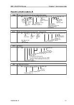
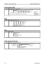
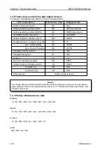
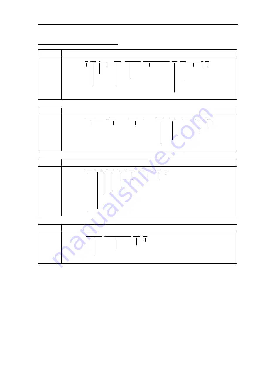
Waypoint Latitude/Longitude, ID
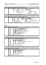
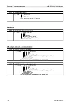
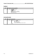
RMB
Recommended minimum navigation information
a*hh<CR><LF>
Status
Not used
Destination
Not used
Check sum
A=Valid
w aypoint longitude,
Mode indicator
V=Data
Direction
E/W
A/D=valid
Invalid
to steer
Destination w aypoint
E/M/S/N=invalid
L/R
latitude, N/S
Bearing to
Cross track
Destination w aypoint ID
destination,
error
degrees natical miles
Range to destination,
nautical miles
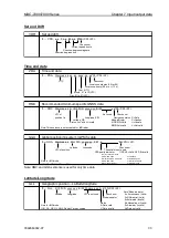
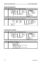
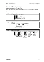
BWC
Bearing and distance to waypoint – Great circle
a*hh<CR><LF>
UTC of
Waypoint
Waypoint
Check sum
observation
latitude
longitiude
Mode indicator*
N/S
E/W
Waypoint ID
Distance, nautical miles
Note* Mode indicator
Bearing, digrees magnetic
A/D=Valid
Bearing, digrees true
E/M/S/N=Invalid
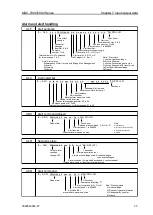
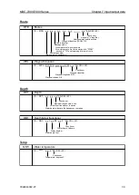
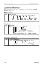
RTE
Routes
*hh<CR><LF>
Check sum
w aypoint "n" identifier
Additional w aypoint identifiers
Waypoint identifire (FROM, TO)
Route identifier
Message mode
C=complete route, all w aypoints
W=w orking route, first listed w aypoint is "FROM"
second is "TO" and remaining are rest of route
Sentence number
Total number of sentences
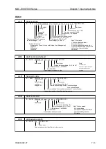
WPL
Waypoint location
*hh<CR><LF>
Check sum
Waypoint identifier
Waypoint longitude, E/W
Waypoint latitude, N/S
c--c
$ -- WPL, llll.ll, N/S, yyyyy.yy, E/W,
c--c,
$ -- RTE, x.x, x.x,
a,
c--c, c--c, c--c, . . . . . . c--c
x.x, x.x, x.x, A,
$ --
BWC,
hhmmss.ss, llll.ll, N/S, yyyyy.yy, E/W, x.x, T, x.x, M, x.x, N,
a,
c--c, c--c, llll.ll, N/S, yyyyy.yy, E/W,
$ -- RMB, A, x.x,
Summary of Contents for MDC-7006
Page 1: ......
Page 2: ......
Page 44: ...Chapter 3 installation method MDC 7000 7900 Series 3 24 0092669002 07 Unit mm inch MRM 108 ...
Page 96: ... This page intentionally left blank ...
Page 134: ... This page intentionally left blank ...
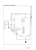
Page 155: ...0092669002 07 A 1 INTER CONNECTION DIAGRAM RB807 ...
Page 156: ...A 2 0092669002 07 INTER CONNECTION DIAGRAM RB808 ...
Page 157: ...0092669002 07 A 3 INTER CONNECTION DIAGRAM RB809 ...
Page 158: ...A 4 0092669002 07 INTER CONNECTION DIAGRAM MRD 108 MRO 108 ...
Page 159: ...0092669002 07 A 5 INTER CONNECTION DIAGRAM MRM 108 MRO 108 ...
Page 160: ......

