Chapter 3 installation method
MDC-7000/7900 Series
3-28
0092669002-07
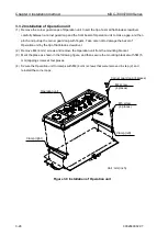
3.3.2 Installation of Operation unit
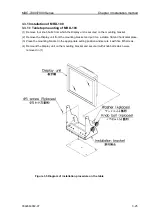
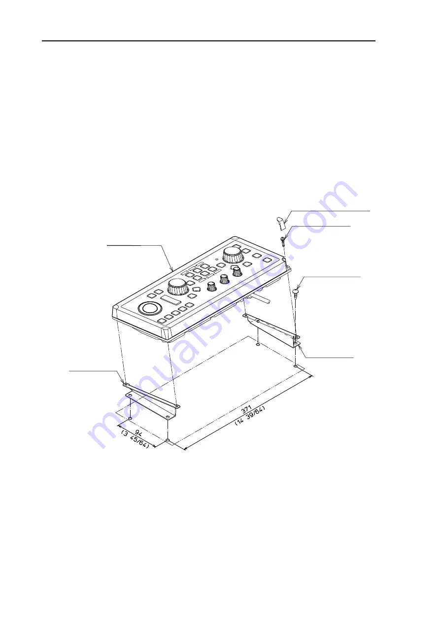
(1) Remove the corner guard caps of Operation unit. Insert the tip of a small flat-blade screwdriver
carefully between a corner guard cap and the front bezel of Operation unit to make a gap, and then
pinch and pull up the corner guard cap with fingers. Take care not to damage the bezel of
Operation unit by the tip of flat-blade screwdriver.
(2) Remove M4 (4 mm) screws and remove the Operation unit from the mounting bracket.
(3) Mark the place as shown in the following figure, and then secure the mounting bracket with 5M (5
mm) tapping screws at four places.
(4) Secure the Operation unit to clamps with M4 (4 mm) screws that were removed in step (2) and
reinstall the corner caps.
Figure 3.9 Installation of Operation unit
Corner guard cap (4 places)
Operation unit
M4 screw
(4 places)
M5 screw
(4 places)
Clamp (left)
Clamp (right)
Unit : mm(inch)
Summary of Contents for MDC-7006
Page 1: ......
Page 2: ......
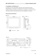
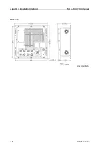
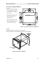
Page 44: ...Chapter 3 installation method MDC 7000 7900 Series 3 24 0092669002 07 Unit mm inch MRM 108 ...
Page 96: ... This page intentionally left blank ...
Page 134: ... This page intentionally left blank ...
Page 155: ...0092669002 07 A 1 INTER CONNECTION DIAGRAM RB807 ...
Page 156: ...A 2 0092669002 07 INTER CONNECTION DIAGRAM RB808 ...
Page 157: ...0092669002 07 A 3 INTER CONNECTION DIAGRAM RB809 ...
Page 158: ...A 4 0092669002 07 INTER CONNECTION DIAGRAM MRD 108 MRO 108 ...
Page 159: ...0092669002 07 A 5 INTER CONNECTION DIAGRAM MRM 108 MRO 108 ...
Page 160: ......

