MDC-7000/7900 Series
Chapter 4 Setup after installation
0092669002-07
4-19
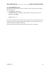
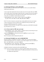
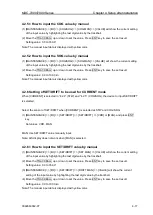
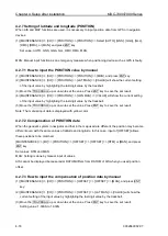
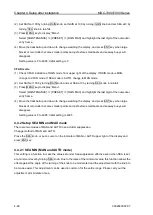
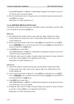
(4) [MAINTENANCE] => [I/O] => [POSITION] => [OFFSET] => [LON MAN] => [VALUE] will show the
current setting of the input value by highlighting the last digit value by the trackball.
(5) Move the TRACKBALL up or down to set the value. Press ENT key to save the set result.
Setting value: 1.000W to 1.000E
For setting in [MAN] mode, set the radar in N-UP mode to display map. Transmit radar and display the
echo. Then, comparing the landscape of the radar image with the map, input offset values of latitude
and longitude with the trackball. When a value is input, it moves right and left. Compensation can be
easily applied.
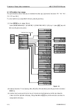
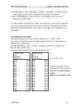
4.2.8 Setting of serial output
Following serial data sentences can be output from NMEA port (J3, J5, J6, OP1 or OP2).
Note: GYRO and OTHER port will be active when the junction box JB-35 is connected to NAV port.
Make selection by following steps.
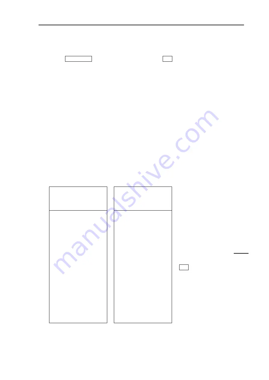
Select [MAINTENANCE] => [I/O] => [OUTPUT] => [OUTPUT J3], [OUTPUT J5], [OUTPUT J6],
[OUTPUT OP1] or [OUTPUT OP2].
Then indicate following submenu by moving the trackball to the right.
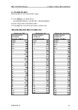
Highlight numeral value and enter
desired period for desired sentence.
No output is available by 0.0 sec
setting.
ENT key press validates the value.
>MAINTENANCE
>MAINTENANCE
>I/O
>I/O
>OUTPUT
>OUTPUT
>OUTPUT J3
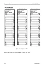
>OUTPUT xxxx
xxxx: J5, J6, OP1 or OP2
DTM
0.0sec
DTM
0.0sec
EVE
1.0sec
EVE
0.0sec
GLL
0.0sec
GLL
0.0sec
HBT
5.0sec
HBT
0.0sec
HDT
0.0sec
HDT
0.0sec
OSD
1.0sec
OSD
0.0sec
POS
0.0sec
POS
0.0sec
ROT
0.0sec
ROT
0.0sec
RSD
1.0sec
RSD
0.0sec
THS
0.0sec
THS
0.0sec
TLB
5.0sec
TLB
0.0sec
TLL
0.0sec
TLL
0.0sec
TTD
0.0sec
TTD
0.0sec
TTM
0.0sec
TTM
0.0sec
VBW
0.0sec
VBW
0.0sec
VDR
0.0sec
VDR
0.0sec
VHW
0.0sec
VHW
0.0sec
VTG
0.0sec
VTG
0.0sec
ZDA
0.0sec
ZDA
0.0sec
Summary of Contents for MDC-7006
Page 1: ......
Page 2: ......
Page 44: ...Chapter 3 installation method MDC 7000 7900 Series 3 24 0092669002 07 Unit mm inch MRM 108 ...
Page 96: ... This page intentionally left blank ...
Page 134: ... This page intentionally left blank ...
Page 155: ...0092669002 07 A 1 INTER CONNECTION DIAGRAM RB807 ...
Page 156: ...A 2 0092669002 07 INTER CONNECTION DIAGRAM RB808 ...
Page 157: ...0092669002 07 A 3 INTER CONNECTION DIAGRAM RB809 ...
Page 158: ...A 4 0092669002 07 INTER CONNECTION DIAGRAM MRD 108 MRO 108 ...
Page 159: ...0092669002 07 A 5 INTER CONNECTION DIAGRAM MRM 108 MRO 108 ...
Page 160: ......

