Chapter 4 Setup after installation
MDC-7000/7900 Series
4-24
0092669002-07
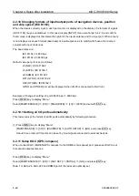
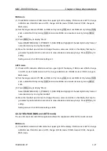
4.3 Setup SECTOR MUTE mode (Cannot use while transmitting)
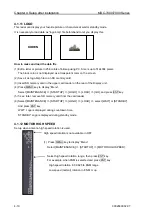
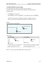
SECTOR MUTE is the function enabling user to stop transmission to designated direction when there
are hazardous objects near antenna location or near a human body.
When using SECTOR MUTE, it takes longer time to detect optimum value in auto tuning at the start of
transmission and change of range. Therefore manual tuning is recommended to use when using
SECTOR MUTE.
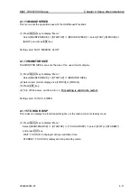
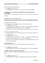
SECTOR MUTE mode ON or OFF
Press MENU
key to display “Menu”.
Select [MAINTENANCE] => [SECTOR MUTE] => [MUTE] => [ON or OFF] => and press ENT key.
Setup starting angel setup of SECTOR MUTE
Press MENU
key to display “Menu”.
Select [MAINTENANCE] => [SECTOR MUTE] => [START] => select 0 to 359°, and press ENT key.
Setup ending angle of SECTOR MUTE
Press MENU
key to display “Menu”.
Select [MAINTENANCE] => [SECTOR MUTE] => [END] => select 0 to 359°, and press ENT key.
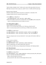
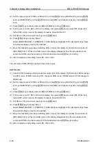
4.4 Setup PRESET
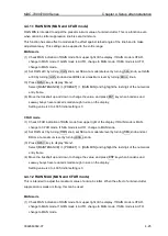
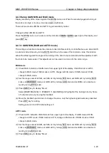
4.4.1 Setup RAIN MIN and MAX mode
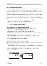
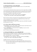
There are two modes of MAN and CFAR in anti-rain clutter mode.
Change method of MAN and CFAR.
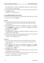
Press the RAIN knob, or put a cursor on the indicator of MAN or CFAR upper right of the display and
press ENT key.
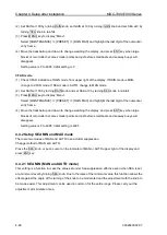
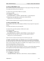
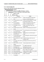
>MAINTENANCE
>I/O
>SERIAL MONITOR.
>ALL
NAV
EPFS
SDME
GYRO
OTHER
AIS
Summary of Contents for MDC-7006
Page 1: ......
Page 2: ......
Page 44: ...Chapter 3 installation method MDC 7000 7900 Series 3 24 0092669002 07 Unit mm inch MRM 108 ...
Page 96: ... This page intentionally left blank ...
Page 134: ... This page intentionally left blank ...
Page 155: ...0092669002 07 A 1 INTER CONNECTION DIAGRAM RB807 ...
Page 156: ...A 2 0092669002 07 INTER CONNECTION DIAGRAM RB808 ...
Page 157: ...0092669002 07 A 3 INTER CONNECTION DIAGRAM RB809 ...
Page 158: ...A 4 0092669002 07 INTER CONNECTION DIAGRAM MRD 108 MRO 108 ...
Page 159: ...0092669002 07 A 5 INTER CONNECTION DIAGRAM MRM 108 MRO 108 ...
Page 160: ......

