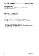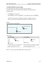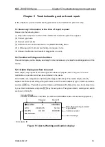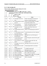
Chapter 4 Setup after installation
MDC-7000/7900 Series
4-26
0092669002-07
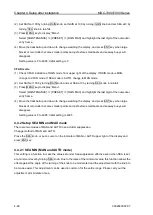
(2) Set RAIN at 100 by turning RAIN knob, set GAIN at 100 by turning GAIN knob and set SEA at 0 by
turning SEA knob in rainfall.
(3) Press MENU
key to display “Menu”.
Select [MAINTENANCE] => [PRESET] => [RAIN MAX] and highlight the last digit of the numerical
entry frame.
(4) Move the trackball up and down to change watching the display, and press ENT key when large
blocks of rain clutter become smaller points and just before small boats and seaway buoys will
disappear.
Setting value is 0 to 4095: Initial setting is 0
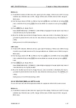
CFAR mode
(1) Check CFAR indication of RAIN mode from upper right of the display. If RAIN mode is MAN,
change to CFAR mode. If SEA mode is AUTO, change to MAN mode.
(2) Set RAIN at 100 by turning RAIN knob and set SEA at 0 by turning SEA knob in rainfall.
(3) Press MENU
key to display “Menu”.
Select [MAINTENANCE] => [PRESET] => [RAIN MAX] and highlight the last digit of the numerical
entry frame.
(4) Move the trackball up and down to change watching the display, and press ENT key when large
blocks of rain clutter become smaller points and just before small boats and seaway buoys will
disappear.
Setting value is 0 to 4095: Initial setting is 4095
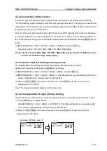
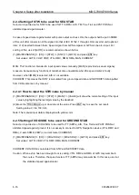
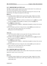
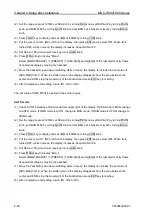
4.4.2 Setup SEA MIN and MAX mode
There are two modes of MAN and AUTO in sea clutter suppression.
Change method of MAN and AUTO.
Press the SEA knob, or put a cursor on the indicator of MAN or AUTO upper right of the display and
press ENT key.
4.4.2.1 SEA MIN (MAN and AUTO mode)
This setting is a function to make the value set under Sea suppression effective even when SEA is set
at a minimum level by turning SEA knob. Due to the raise of the minimum value, this function allows the
effect against the angle of the turning of the knob to be moderated and the adjustment with the knob to
be made easier. This adjustment can be used in common for the entire range. Please carry out the
adjustment at mild state of sea.
Summary of Contents for MDC-7006
Page 1: ......
Page 2: ......
Page 44: ...Chapter 3 installation method MDC 7000 7900 Series 3 24 0092669002 07 Unit mm inch MRM 108 ...
Page 96: ... This page intentionally left blank ...
Page 134: ... This page intentionally left blank ...
Page 155: ...0092669002 07 A 1 INTER CONNECTION DIAGRAM RB807 ...
Page 156: ...A 2 0092669002 07 INTER CONNECTION DIAGRAM RB808 ...
Page 157: ...0092669002 07 A 3 INTER CONNECTION DIAGRAM RB809 ...
Page 158: ...A 4 0092669002 07 INTER CONNECTION DIAGRAM MRD 108 MRO 108 ...
Page 159: ...0092669002 07 A 5 INTER CONNECTION DIAGRAM MRM 108 MRO 108 ...
Page 160: ......


