MDC-7000/7900 Series
Chapter 3 Installation method
0092669002-07
3-31
3.3.3 Installation of MRM-108
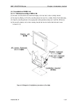
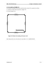
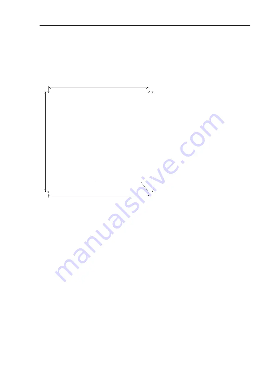
The Processor unit MRM-108 can be mounted on a table or a panel. The procedure is as follows.
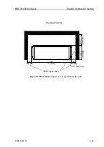
(1) Drill four nut-holes with the size shown in Figure 3.13.
(2) Fit the Processor unit.
4mm screw for 4holes
308 mm
12 1/8 inch
308 mm
12 1/8 inch
3
0
8
m
m
1
2
1
/8
i
n
ch
3
0
8
m
m
1
2
1
/8
i
n
ch
Note: Please set the menu of monitor size to use. Refer to
“4.1.14 MONITOR SIZE”.
Figure 3.13 Holes for mounting a Processor unit
Summary of Contents for MDC-7006
Page 1: ......
Page 2: ......
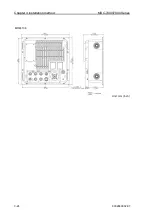
Page 44: ...Chapter 3 installation method MDC 7000 7900 Series 3 24 0092669002 07 Unit mm inch MRM 108 ...
Page 96: ... This page intentionally left blank ...
Page 134: ... This page intentionally left blank ...
Page 155: ...0092669002 07 A 1 INTER CONNECTION DIAGRAM RB807 ...
Page 156: ...A 2 0092669002 07 INTER CONNECTION DIAGRAM RB808 ...
Page 157: ...0092669002 07 A 3 INTER CONNECTION DIAGRAM RB809 ...
Page 158: ...A 4 0092669002 07 INTER CONNECTION DIAGRAM MRD 108 MRO 108 ...
Page 159: ...0092669002 07 A 5 INTER CONNECTION DIAGRAM MRM 108 MRO 108 ...
Page 160: ......

