background image

Chapter 4 Target (AIS, TT and Trial manoeuvre)                 

MDC-7000/7900 Series


0093169010-10 

4-4 

R1

Number

Reference number

Label

5
Sarah J

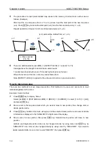
Set AIS ID DISP TYPE 

ID can be displayed with AIS target. 

Set items: NUMBER, NAME, MMSI, IMO and CALLSIGN 


Set TT ID DISP TYPE 

ID can be displayed with TT (ARPA) target. 

Set items: NUMBER and LABEL 


Refer to 4.3 TT (ARPA) 

“Reference target acquisition” 

about reference number. 

ECHO

VECT

NUMBER

ON/OFF

TRAIL

CPA/TCPA

NAME

ON/OFF

DISPLAY

ANCH

MMSI

ON/OFF

ALARM

AIS ID DISP TYPE

IMO

ON/OFF

TARGET

TT ID DISP TYPE

CALLSIGN

ON/OFF

NAV TOOL 

ID DISP SIZE

MAP 

INPUT RNG

BRILL

ASSOCIATION

SYSTEM

AUTO ACQ AREA

MAINTENANCE

  BRG REL

  WIDTH

  RNG

  DEPTH

AIS

TT

TRIAL MONOEUVRE

ECHO

VECT

TRAIL

CPA/TCPA

DISPLAY

ANCH

ALARM

AIS ID DISP TYPE

TARGET

ANCH

NUMBER

ON/OFF

NAV TOOL 

TT ID DISP TYPE

LABEL

ON/OFF

MAP 

ID DISP SIZE

Summary of Contents for MDC-7010

Page 1: ......

Page 2: ......

Page 3: ...11 8 0093169010 08 2017 09 25 Configuration items 9 0093169010 09 2018 03 06 Configuration items Chapter 11 10 0093169010 10 2018 03 13 MDC 7000 7900 OC Series MDC 7000 7900 Series Chapter 2 Chapter 10 Document No Revised Version Norm When part of the document needs to be revised the document has advanced revision number The document No is indicated at the lower right side on the cover and at the ...

Page 4: ...l ones and some parts may be omitted Koden is not liable for damages and troubles arisen from misunderstanding of the contents in this manual Koden is not liable for any damages caused by earthquake lightning wind and flood damage and fire for which Koden is not responsible and actions by third parties other accidents customer s unintended error abuse and the use under other abnormal conditions Ko...

Page 5: ...t there is a risk of death or serious injury caused by electric shock when not dealt with it correctly Caution Symbol This symbol denotes that there is a risk of slight injury or damage of device when not dealt with it correctly Prohibition Symbol This symbol denotes restriction of the specified conduct Description of the restriction is displayed near the mark IMPORTANT Important Symbol This mark ...

Page 6: ...y or death may occur due to high voltage Make sure main power is off and a label Work In Progress is attached to the breaker powering the system Caution related to dust Inhaling dust may cause A respiratory disease When cleaning the inside of equipment be careful not to inhale dust Wearing a safety mask is recommended When choosing equipment location Do not install the equipment where it is excess...

Page 7: ...t some kind of medical devices such as heart pacemakers are sensitive even under the low energy electromagnetic wave Any personnel with such a device should keep away from the electromagnetic wave generating position at all times Specified power density and distance from the radar in accordance with the provision as specified in IEC 60945 Model name Transmission power Antenna length 100W m2 50W m2...

Page 8: ... damage Caution related to remaining high voltage A high voltage may remain in the capacitor for several minutes after system is powered off Before inspecting inside wait at least 5 minutes after powering off or discharging the remaining electricity in an appropriate manner Then start the work The information displayed in this unit is not provided directly for your navigation For your navigation b...

Page 9: ...itting operation such as arcing at its initial operation after long period of storage and make the operation more difficult 1 Extend preheat time as long as possible preferably 20 to 30 minutes 2 Set the pulse width to the shortest one and start the operation When the operation in the shortest pulse is stable then go to operation in longer pulse and repeat the similar step until the operation reac...

Page 10: ...ollection rules may be different depending on each municipal district Obey the directions of each district Disposal of this radar This radar shall be disposed according to the municipal regulations or rules A high energy density lithium ion battery is installed in this radar Improper disposal of a lithium ion battery is discouraged as the battery has a possibility of short circuiting If it gets we...

Page 11: ...lt settings These alarms are disengaged by pressing OFF key temporarily however the alarms are activated again next time the radar is start up Disengage the alarm detection function on start up by the following Once set the alarm is not detected next time the radar is started up Press MENU key to display Menu Select ALARM ALARM ON OFF I O HDG INPUT OFF and press ENT key Select ALARM ALARM ON OFF I...

Page 12: ... 1 1 Radar Display 1 1 Upper left corner 1 1 Upper right corner 1 2 Lower left corner 1 2 Lower right corner 1 2 Own ship data 1 3 Target status 1 3 Target and MAP information area 1 4 Assistant display Navigation information 1 5 Alarm display area 1 6 Alarm display area Navigation graph 1 8 Alarm status 1 8 1 2 Operation Unit 1 9 1 3 Menu usage 1 11 Turn MENU on and off 1 11 Select menu item 1 11...

Page 13: ...f CFAR and MAN 2 11 CFAR Constant False Alarm Rate adjustment 2 11 RAIN MAN manual adjustment 2 12 2 9 Change transmission pulse width SP LP 2 13 2 10 Select Display Mode 2 14 For H UP Head up mode 2 14 For C UP Course up mode 2 15 For N UP North up mode 2 16 For relative motion RM and true motion TM 2 17 Reset true motion 2 18 2 11 Ground and Sea stabilization 2 19 SEA Sea stabilization 2 19 GND ...

Page 14: ...40 2 23 Echo process 2 41 Correlation image echo process 2 41 2 24 Echo expansion 2 42 2 25 Interference rejection IR 2 43 2 26 Video contrast 2 43 2 27 Noise rejection 2 44 2 28 Echo color rejection 2 44 2 29 Pulse width 2 45 2 30 Receiving Radar Beacons SART and Radar Enhancer 2 46 2 31 Inter switch 2 48 2 32 Cursor data 2 50 CURSOR setting menu 2 50 2 33 Reference position and Display center 2 ...

Page 15: ... How to set guard zone alarm 3 7 3 4 Nav line cross 3 8 How to edit 3 8 How to move nav line 3 9 How to add 3 10 How to delete 3 11 How to clear 3 11 3 5 Alarm List 3 12 3 6 Alarm History list 3 13 3 7 Alarm on off TT and AIS 3 14 Chapter 4 Target AIS TT and Trial manoeuvre 4 1 4 1 Common setting 4 1 VECTOR REL TRUE 4 1 CPA TCPA alarm 4 3 LOST ALARM 4 3 Set AIS ID DISP TYPE 4 4 Set TT ID DISP TYPE...

Page 16: ...TT target 4 19 Delete all TT targets 4 19 Reference target acquisition 4 20 Types of tracked target symbol 4 22 TEST TGT 4 23 4 4 Trial manoeuvre 4 34 Chapter 5 Nav tool 5 1 5 1 Guard line 5 1 5 2 HL blink 5 2 5 3 Stern line 5 2 5 4 Barge icon 5 3 Chapter 6 Map operation 6 1 6 1 MAP function display ON or OFF 6 1 6 2 OWN SHIP PAST TRACK 6 1 How to Clear OWN SHIP PAST TRACK 6 2 6 3 Target track pas...

Page 17: ...CAL time 7 1 7 3 User memory 7 2 Change USER memory 7 2 How to save to memory 7 2 Edit User Name 7 2 Default User setting 7 2 7 4 Sound setting 7 3 Sound ON OFF 7 3 Sound frequency 7 3 Key click ON OFF 7 3 External buzzer setting 7 3 7 5 LANGUAGE select 7 4 7 6 DISPLAY INFOMATION DISP INFO 7 4 7 7 HELP window ON OFF 7 5 7 8 MAINTENANCE MENU 7 5 7 9 BACKUP of Setup data Cannot be used while transmi...

Page 18: ... 9 6 No radar video display 9 7 9 7 Frozen Display 9 8 Indication of presentation failure 9 8 9 8 About alarms 9 9 Alarm list 9 10 Operation note 9 14 Chapter 10 Specifications 10 1 10 1 Antenna and Scanner unit 10 1 10 2 Display Processor and Operation unit 10 2 10 3 External view and dimensions 10 3 Chapter 11 Appendix 11 1 11 1 Menu tree 11 1 11 2 Special key operations 11 13 11 3 Details of th...

Page 19: ... 10 xvii 11 5 4 Serial data input output specification AIS 11 32 11 5 5 Radar input output signal specification 11 33 11 5 6 Talker device code of the data output devices 11 34 11 5 7 Priority of talker device code 11 34 Chapter 12 Index 12 1 ...

Page 20: ...he newly developed radar dedicated LSI Large Scale Integration A slim Display unit using liquid crystal technology Stable indication and reliable acquisition of small targets Clear distinction between a moving target and land by true trail display Provision of multi targets TT ARPA information and AIS information Various models for selection of optimum radar for your needs Capable of adjusting gai...

Page 21: ... 12 Quick reference MDC 7000_7900 OC QR E RW701A 04 4feet RW701A 06 6feet RW701B 09 9feet RB717A 6kW MDC 7060 RB718A 12kW MDC 7010 RB719A 25kW MDC 7020 MDC 7960 7910 7920 No Name Type 1 Antenna 2 Scanner 3 Display unit MRD 108 4 Operation unit with connecting cable MRO 108 5 Connecting cable 242J159098B 15M 6 DC power cable CW 259 2M 7 Spare parts SP MRD MRM 108 8 Installation material M12 BOLT KI...

Page 22: ...tor and a 6 pin water resistant connector cable for data 9 CW 376 5M With a 6 pin water resistant connector and one end plain cable for data 10 CW 387 5M With a 8 pin water resistant connector and one end plain cable for AIS 11 CW 561 10M 30M With 12 pin water resistant connectors at both ends cable for remote display 12 CW 576 0 5M With a 10 pin water resistant connector and D Sub connector analo...

Page 23: ...re freeze detection REF position number 1 4 REF position CCRP ANT When there is not alarm information this area can display the graph of navigation data EBL1 Upper left corner Upper right corner Lower left corner Lower right corner Own ship data Target status Target and MAP Information area Assistant display Navigation Information Alarm display Nav graph area Heading line ERBL EBL2 OFFSET Range Ri...

Page 24: ...RM2 distance Distance of selected No 4 PI Inter switch mode TUNE setting GAIN setting SEA setting RAIN setting PICTURE setting PROCESS setting EXPANSION setting VIDEO mode setting Sector MUTE ON MAP function display TRAIL TRUE REL TRAIL TIME Own Ship Past Track ON EBL1 EBL2 EBL1 active mark EBL bearing Offset EBL move mode TM RM Selected PI Active PI Bearing of selected PI ...

Page 25: ... CTW or COG STW or SOG Set and Drift Own ship position Vector Time Vector REL TRUE Limit CPA Limit TCPA AIS and TT Lost Alarm Association setting AIS ON TT ON AIS and TT Past position Indication Mode REL TRUE Indication Time Activity AIS Filter Icon Indication AtoN AIS AIS Auto Acquisition by CPA TCPA AIS Auto Acquisition by Range 0 0NM to 64 0NM ...

Page 26: ...or MAP COAST LINE NAV LINE ROUTE EVENT MKR and AREA information is displayed this data can be changed by selecting with cursor and pressing ENT key Change TT shape Cursor and press ENT key Edit LAT LON data Change Color Deletion of indication data Line indication between own ship position and marker point Comment input ...

Page 27: ...G TGT and SEL CPA It is displayed with the nearest first from the top of display TCPA It is displayed with the shortest first from the top of display RNG It is displayed with the nearest first the top of display TGT It is displayed with the nearest to the selected target first from the top of display SEL It is displayed with the selected target first from the top of display NAV INFO TGT OUTLINE TG...

Page 28: ...larm Alarm list Refer to 9 8 About alarms Alarm list ALARM Displayed with red In case of unacknowledged alarm icon and ALARM of priority will be flashing and 3 short audible signals will be repeating every 7 sec In case of silenced alarm audible signals will be stopping If silenced alarm condition keeps more than 30sec silence alarm condition will cancel Type of ALARM icons Active Unacknowledged a...

Page 29: ...Type of WARNING icons Active Unacknowledged warning Active Silenced warning Active Acknowledged warning Active Responsibility transferred warning Rectified Unacknowledged warning CAUTION Displayed with yellow In case of CAUTION status icon and CAUTION of priority is not flashing and audible signal is silent Type of CAUTION icon Caution WARNING A 9999999 UTC 15 10 14 16 23 RADAR 1 MESSAGE CAUTION A...

Page 30: ...wind direction and speed It is necessary to input VDR sentence to display set and drift Echo level monitor shows the signal level of EBL1 direction Alarm status The icon of alarm status will be displayed at the lower left corner of the display Alarm icon Icon name Setting method Refer to Chapter 3 Alarm Echo alarm Refer to 3 1 Echo alarm Map area alarm Refer to 3 2 Map area alarm Nav line cross al...

Page 31: ...day or night 6 EBL1 key EBL1 on and off 7 EBL2 key EBL2 on and off 8 BRILL key Display brilliance adjust mode on and off 9 EBL BRILL knob Adjust EBL1 EBL2 or display brilliance 10 OFFSET lamp Status lamp of offset EBL mode on 11 RAIN knob Reduce rain clutter 12 SEA knob Reduce sea clutter 13 GAIN knob Adjust radar receiver gain 14 FUNCTION keys F1 F6 Quick short cut menu access 15 VRM1 key VRM1 on...

Page 32: ...x lines 20 ERBL key Electronic range and bearing line on and off 21 OFF key Erase heading line stop alarm sound etc 22 MENU key Turn MENU on and off 23 ACQ key Start manual TT acquisition 24 ENT key Key most often used to make a selection 25 RANGE key Change radar range scale 26 MODE key Change display mode HU NU CU 27 OFF CENT key Off center mode on and off 28 TRACKBALL Used to make MENU selectio...

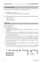
Page 33: ... value of selected item will show 5 Select desired value then press ENT key Note Pay attention that ENT key must be pressed for selected item to take effect 6 Move trackball to the left to return to previous menu To exit from menu press MENU key again Example of menu display Note Menu setup value is stored in the non volatile memory inside the radar Therefore no setup operation is required after p...

Page 34: ...CE menu are not available during transmission therefore they are greyed out 1 4 Cursor Access usage Basic radar functions can be operated by using the trackball and ENT key without using menu This function is effective for the operation with USB Mouse Trackball from the remote place Move cursor on a grey item with trackball then press ENT key Standby Standby Transmission Transmission ...

Page 35: ...0 7960 7010 7910 2 MDC 7020 7920 The brilliance of the display is set to the previous value of the last power off During operation POWER LAMP under POWER ON OFF key lights up red Note The power source shall not be turned off until operational window is displayed Power OFF Press POWER ON OFF key for two sec for power off SHUTDOWN message appears at the center of the display release POWER ON OFF key...

Page 36: ...play brilliance can also be changed in five steps by pressing EBL knob Operation unit Brilliance 1 Press PANEL key 2 The PANEL adjustment window will appear in the upper left of the display 3 Turn VRM knob clockwise to increase the lighting of the panel brilliance Turn VRM knob counterclockwise to decrease the lighting of the panel brilliance The panel brilliance can also be changed in five steps ...

Page 37: ...box at the upper left corner of the display using trackball and press ENT key Radar system will start transmission The status of STANDBY changes to TRANSMIT Transmission OFF Press STBY TX key or select the TRANSMIT box at the upper left corner of the display using trackball and press ENT key to stop transmission The status of TRANSMIT returns to STANDBY at upper left of the display Operation of ST...

Page 38: ...chever is shown of tune indicator at upper right of the display using trackball and press ENT key Optimized value setup method Adjustment shall be performed based on stable echo object such as from land Land is used in following explanation 1 Set RAIN and SEA at 0 2 Set lower GAIN until land echo almost disappears 3 Press GAIN TUNE knob until light around knob turns red Tune value box will appear ...

Page 39: ...nge key to zoom in the picture to magnify and to observe closer to Antenna position Model specific ranges are as shown below Model name MDC 7020 7920 Max output 25 kW MDC 7010 7910 Max output 12 kW MDC 7060 7960 Max output 6 kW Range NM 0 125 0 25 0 5 0 75 1 5 3 6 12 24 32 48 64 96 32NM and 64NM is for 6kW 12kW only 96NM is for 25kW only Change range unit NM km sm kf ky The unit of range measureme...

Page 40: ...GAIN to original position each time GAIN is changed to maintain target recognition In the short distance area where anti SEA is effective recognize target by adjusting MAN SEA When suppressing RAIN clutter rain or snow adjust GAIN knob and RAIN knob side by side GAIN state is displaying in the upper right of the display Selection of MAN GAIN and AUTO GAIN By GAIN knob When the GAIN knob is pressed...

Page 41: ... increase receiving gain Turn GAIN knob counterclockwise to decrease receiving gain Up Down Gain Note Decrease gain for shorter range and dense targets Increase gain for long range targets and small target however take care in not using too much gain and losing targets in the surrounding noise Own ship Land Result picture after adjustment a GAIN knob Own ship Land Own ship Land ...

Page 42: ...hips and buoys from sea clutter Anti SEA is effective to suppress false echoes and ground clutter in short distance However adjustment of GAIN should be used beyond effective coverage of anti SEA If target echoes are masked by excessive false echoes within anti SEA effective area then adjust MAN SEA to confirm it Excessive anti SEA may lose echoes from small ships and buoys So return to appropriat...

Page 43: ...d manually By using SEA knob suppress this effect and make targets seen easier SEA state is displayed in the upper right of the display 1 Turn SEA knob clockwise to increase anti sea clutter effect Turn SEA knob counterclockwise to decrease anti sea clutter effect 2 Turn SEA knob clockwise until even low weak SEA clutter is displayed by observing the display 3 Adjust SEA knob from time to time to ...

Page 44: ... Small target becomes harder to detect when RAIN is used together with SEA Therefore please adjust them carefully The echo process refer to 2 23 Echo process is useful to reject rain clutter Be careful when the echo process is active high speed targets are harder to detect than stationary ones The performance of radar detection range is degraded by rain as shown in the figure below The details of ...

Page 45: ... RAIN knob clockwise to increase anti clutter effect Turn RAIN knob counterclockwise to decrease anti clutter effect Strong Weak RAIN 2 Turn RAIN knob clockwise to get even low weak clutter while watching the display Note In the case of CFAR mode the gain adjustment is not possible Adjust SEA knob to suppress remaining sea clutter In typical environment CFAR should be turned all the way down via R...

Page 46: ...y turning RAIN knob clockwise Adjust RAIN so that sea clutter is lightly visible 4 Intensity of RAIN clutter is affected by weather Adjust by RAIN knob according to weather change by watching the display Note In typical environment RAIN should be turned all the way down via RAIN knob and no white level should be indicated by RAIN window Turning the knob to the right shows profiles of the targets h...

Page 47: ...high resolution and is effective for dense targets The long wide pulse width used in long range has high gain sensitivity and is effective for detecting small targets Two different pulse widths are set by default in the following ranges 0 75NM 1 5NM 3NM and 6NM Ranges 0 25NM and below and 12NM and above are setup with same pulse width in SP and LP Note Refer to 2 29 Pulse width to set pulse width ...

Page 48: ... up mode Heading line is always oriented toward the top of the display This mode is based on the bow of the ship and is suitable to monitor targets because targets are seen as they are in navigating own ship When heading signal is connected H UP works by stabilized mode STAB H UP Note This is a presentation mode stabilized in azimuth with fixed origin in which the radar image is oriented up toward...

Page 49: ...aring scale showing 000 relative bearing Target trails can use only relative mode For C UP Course up mode When choosing Course up mode current heading becomes the course at the top of the display and a moving heading line indicates actual This mode is used to navigate towards a specified course It easily shows any deviation of own ship from the specified course Note This is an azimuth stabilized p...

Page 50: ...top of the display A north oriented representation makes it easy to reference with a chart Note This is an azimuth stabilized presentation in which north on the bearing scale remains fixed vertically above the CCRP The heading line points from the CCRP to own ship s referenced heading on the bearing scale The true bearing of any target on the display is measured from north ...

Page 51: ...icates the motion of the target with respect to the specified bearing Fixed targets that do not move in any direction stay on the display and all the moving targets move on the display Note The heading always continues to move So no true motion TM is available for H UP Relative motion RM The antenna position is fixed and the other surrounding targets move on the display This is useful to monitor t...

Page 52: ...range scale own ship position is to reset to the course over water or to the opposite direction of the course over ground Reset true motion Own ship display position can be manually reset when in true motion operation at any given point by following procedure Press MENU key to display Menu Select DISPLAY TM RESET and press ENT key 75 Antenna position 75 Antenna position Antenna position direction ...

Page 53: ...upper right of the display becomes CTW STW STW is relative speed of the ship against water surface in the heading direction Information from SDME speed and distance measuring equipment like LOG is inputted by serial data VBW or VHW Single axis water log indicated as LOG on the display cannot detect the effect of leeway When speed information is interrupted for 30 seconds from SDME for any reason o...

Page 54: ...ship with reference to the land Two dimensional GND SDME device like dual axis LOG and EPFS electronic position fixing system provide information for serial input If both serial sentence data of VTG EPFS and VBW SDME are available then VBW takes priority If failure of EPFS or SDME interrupts the speed information for 30 seconds or if the ground status flag or VTG indicator flag is invalid then the...

Page 55: ...tance to a target 1 Press MENU key to display Menu Select NAV TOOL RR RR ON and press ENT key Note RR display can be changed directly in the upper left of the display by moving cursor and pressing ENT key Note When NAV TOOL BRG TRUE REL TRUE is selected 0 of the range rings indicates North direction While when REL is selected it indicates heading direction RR on 1 means range rings interval RR 1 N...

Page 56: ...VRM knob clockwise or counterclockwise respectively Note Turning VRM knob while pressing it changes the range quickly 3 Another press of VRM1 key will make the circle disappear 4 Press VRM2 key to activate the dotted line circle of VRM2 Operation procedure and distance display are the same as VRM1 5 If you want to display both VRM1 and VRM2 simultaneously press VRM1 key and VRM2 key Then both the ...

Page 57: ... EBL knob to adjust the line on the desired target The bearing value changes at the same time and you can read the bearing of the target Note Turning EBL knob while pressing it changes the bearing quickly Clockwise Counter clockwise EBL knob 3 Another press of EBL1 key and the dashed line disappears and the bearing value on the lower left of the display also disappears 4 Press EBL2 key and the bea...

Page 58: ...ffset the color of OFFSET lamp at the lower right of EBL knob changes from green to red and the TM or RM mark is added right of the numerical figures TM means true motion and RM means relative motion of OFFSET EBL1 and EBL2 The motion selection can be changed by NAV TOOL EBL EBL1 OFFSET or EBL2 OFFSET select RM or TM and press ENT key 4 Press EBL knob again and the base point returns to the refere...

Page 59: ... Bearing scale and CURSOR The settings available in the true bearing with the true north of 000 degree and in the relative bearing with the heading of 000 degree 1 Press MENU key to display Menu Select NAV TOOL BRG TRUE REL TRUE or REL and press ENT key EBL PI ERBL and CURSOR can be changed directly on the display by using trackball Relative mode True mode ...

Page 60: ...y to display Menu Select NAV TOOL PI MODE CURSOR and press ENT key PI line number setting 1 PI CURSOR select NORMAL 1 2 3 4 5 6 or 7 and press ENT key NORMAL PI line number is equal to range of range ring Variable range is min equal to range ring one max 50 of selected range 1 to 7 Designated number of PI is displayed Variable range is min 0 max about 1 6 times of selected range PI display side se...

Page 61: ... to display Menu Select NAV TOOL PI LINE LINE Lets user choose line number 1 to 7 and its parameters DISP Lets user turn selected line ON or OFF START RNG Lets user choose starting position of selected line 96 0 to 96 0 NM END RNG Lets user choose ending position of selected line 96 0 to 96 0 NM Select PI PI DISP SIDE select HALF or FULL Select PI PI OPERATION select BULK or INDIVIDUAL When BULK i...

Page 62: ...the bearing and range are shown at the lower left and lower right of the display respectively The lamp color of PI located at the lower left of VRM knob changes from green to red when PI is activated Push VRM knob PI 1 4 000 0 3 000NM PI REL 1 4 3 The range of selected line can be changed by turning VRM knob Note Turning VRM knob while pressing it changes the range quickly Total number of lines Ac...

Page 63: ...Turning EBL knob changes the bearing of a selected line Note Turning EBL knob while pressing it changes the bearing quickly Clockwise Counter clockwise EBL knob PI 1 4 000 0 3 000NM PI REL 1 4 5 To return all PI lines to original position press VRM knob while pressing OFF key ...

Page 64: ... the display with trackball and ENT key without using menu function 1 Press ERBL key and ERBL is displayed ERB L 000 0 1 00NM ERBL REL CURSOR Target B Target A 2 By moving cursor to target A measurement of distance and bearing from target A to target B can be obtained by using VRM knob and EBL knob ERB L 304 2 2 82NM REL Own ship 3 Pressing ENT key while pressing OFF key returns cursor to the refe...

Page 65: ...L OFFSET select CURSOR or TM and press ENT key CURSOR The basic point of ERBL moves with the movement of the cursor TM A cursor position becomes the basic point of ERBL After that a position is fixed without synchronizing cursor movement The operation is limited to a bearing marker and range marker Note TM function needs heading and Lat Lon signal input of the own ship A basic point moves to the p...

Page 66: ...ecting color for each item press ENT key ECHO WHITE YELLOW GREEN MULTI USER1 or USER2 TRAIL BLUE BROWN USER1 or USER2 BKGND PPI BLACK BLUE USER1 or USER2 BKGND DATA BLACK BLUE USER1 or USER2 DATA WHITE GREY USER1 or USER2 OTHERS SCALE NORMAL DARK USER1 or USER2 OS TOOL NORMAL USER1 or USER2 TGT NORMAL USER1 or USER2 COAST LINE NORMAL USER1 or USER2 NAV LINE NORMAL USER1 or USER2 ROUTE NORMAL USER1...

Page 67: ...each item and after adjusting each item with trackball press ENT key You can change the following item s color ECHO TRAIL BKGND PPI BKGND DATA DATA SCALE OS TOOL TGT COAST LINE NAV LINE ROUTE EVENT MKR AREA PAST TRK MONITORED ROUTE LAT LON LINE GPS BUOY CURSOR CHART LAND DEPTH R G B Black 0 0 0 Blue 0 0 255 Green 0 255 0 Light blue 0 255 255 Red 255 0 0 Pink 255 0 255 Yellow 255 255 0 White 255 25...

Page 68: ...1 Select the mode day or night by pressing DAY NIGHT key brightness of which you would like to change 2 Press MENU key to display Menu Select BRILL select ECHO TRAIL BKGND OS TOOL TGT MAP CURSOR DATA and MENU ALERT After adjusting each item with trackball press ENT key Color and brightness settings reset If you want to return the color and brightness settings back to default value please use follo...

Page 69: ...UE are available At the start of trail TRAIL characters at lower left of the display change to yellow When trail time has passed character color turns white Note The trail by its nature records and displays past images The trail does not display right after transmission is started In addition after the change of TIME or after the change of two or more steps in RANGE the trail will disappear becaus...

Page 70: ... as a trail 15 records only the strongest signal levels as a trail CLEAR This is to delete all current trails and restart new trails RANGE KEEP OFF deletes trails when changing range ON does not delete trails when changing range FIRST IMPRESSION The trail is displayed by dark red color during the setting time afterwards will be blue color Setting time OFF 30sec 1min 3min 6min 12min 30min 60min MAR...

Page 71: ... the trail length is equal to the distance between the antenna position and Target 1 then the collision will occur after six minutes N Displaymode N UP RM Target 1 6min 6min Prospect of collision after 6min Antenna position TRAIL REL True display T This mode displays the trail of the moving target over a specified time interval independently from own ship s movement This mode is used to monitor th...

Page 72: ... 2 Off centering is executed by pressing OFF CENT key or move cursor to set value of ON or OFF of OFF CENT at the upper left part of the display and press ENT key 3 The difference of CURSOR and OPPOSITE are as follows CURSOR OPPOSITE Note When CCRP is selected for the reference positon there is possibility that CCRP is located outside of 90 echo image area at OFF CENTER function in short range In ...

Page 73: ...tion shows up on the right of the display Using trackball and ENT key make a selection and save to designated function key PICTUREMODE PROCESS Dedicated function name EXPANSION IR F1 VID F2 OFF NOISEREJ F3 ECHO SART TRAIL T REL F4 TRAIL TRAIL TIME F5 DISPLAY STAB MODE TRAIL RESET F6 ALARM TM RESET TARGET C UPRESET NAV TOOL FERRY MODE ECHO ALARM MAP ECHO ALARM EDIT SYSTEM VECT T REL MAPAREA ALARM V...

Page 74: ...rom PICTURE1 PICTURE2 PICTURE3 NEAR FAR HARBOR ROUGH SEA RAIN or PURE Initial setting of PICTURE MODE PROCESS EXPANSION IR VID PICTURE1 OFF OFF 1 3 PICTURE2 C2 2 OFF 2 PICTURE3 C2 1 OFF 1 NEAR OFF OFF 1 1 FAR C1 2 OFF 4 HARBOR C1 1 2 1 ROUGH SEA C2 OFF 1 1 RAIN C1 OFF 1 1 PURE OFF OFF OFF 1 PROCESS Refer to 2 23 Echo process EXPANSION Refer to 2 24 Echo expansion IR Refer to 2 25 Interference reje...

Page 75: ...ect to suppress the sea and rain snow clutter will be stronger in the order of C1 C2 C3 Process mode A1 A2 A2 mode will display the hardly distinguished target of video signal for a long time than A1 mode Note For confirmation of an image that may be hidden between the waves and the image of a fast ship that appears at a different position for each scan the image may be displayed weaker than the a...

Page 76: ...pper right of the display 1 Move the cursor to set value window of OFF 1 2 3 or 4 of EXPANSION at the upper right part of the display Press ENT key repeatedly until the desired choice appears Note The setting value can be selected from OFF 1 2 3 and 4 and the larger value applies stronger enhance effect Note The enlargement of targets has effect on all echoes So a large target such as land is also...

Page 77: ... the larger value applies stronger interference rejection effect Too much removal effect may also remove small targets Pay attention to that 2 26 Video contrast This is a function to change the relation between the strength of returned echo and their display gradation At VID 1 the difference of signals strength between strong echo and weak echo becomes larger As the numerical figure becomes larger...

Page 78: ...and press ENT key Noise rejection of 2 setting works more effective than 1 2 28 Echo color rejection This radar has a function to remove a color selected by menu operation This effect is to show the strong signal image clearly and to delete the unwanted signal such as noise 1 Press MENU key to display Menu Select ECHO COLOR REJ select OFF or 1 to 14 and press ENT key Selection value 1 Lowest signa...

Page 79: ... S2 M1 M2 M3 L1 L2 S2 M1 M2 M3 L1 L2 6 M2 M3 L1 L2 M2 M3 L1 L2 12 L1 L2 L1 L2 24 L2 L2 32 L2 L2 48 L2 L2 64 L3 L3 SP mode LP mode 25kW Range 0 125 S1 S1 0 25 S1 S2 S1 S2 0 5 S1 S2 M1 S1 S2 M1 0 75 S1 S2 M1 M2 S1 S2 M1 M2 1 5 S1 S2 M1 M2 M3 S1 S2 M1 M2 M3 3 S2 M1 M2 M3 L1 L2 S2 M1 M2 M3 L1 L2 6 M2 M3 L1 L2 M2 M3 L1 L2 12 L1 L2 L1 L2 24 L2 L2 48 L2 L2 96 L3 L3 SP mode LP mode S1 Short pulse 1 S2 Sho...

Page 80: ...5 ECHO SART OFF and press ENT key the setting of above 3 is restored About SART According to the GMDSS Global Maritime Distress and Safety Systems requirement the IMO SOLAS class ships must be equipped with a SART When a ship is in distress a signal will be automatically emitted from the SART so that other ships and or aircrafts can identify its location When your ship equipped with a X band radar...

Page 81: ...ship comes within 1 NM from the SART the fast sweep signal is indicated The position of this echo is displayed 150 m beyond the actual SART position Slow sw eep signal Fast sw eep signal Beam w idth of the radar signal received SART position SART position 1 nm or more beyond the SART position Within 1 nm of SA RT position 9 5GHz 9 2GHz 7 5µs sw eep time 95µs sw eep time Slow sw eep signal Fast sw ...

Page 82: ...TE INTER SWITCH menu cannot be used while transmitting 1 Press MENU key to display Menu Select SYSTEM INTER SWITCH select INTER SWITCH mode and press ENT key Available choices INDEPENDENT MASTER INDEPENDENT SLAVE DUAL MASTER DUAL SLAVE CROSS MONITOR INDEPENDENT MASTER Connection status where one antenna is connected to one radar INDEPENDENT SLAVE Connection status where the dedicated cable is conn...

Page 83: ...rs to which each antenna is connected In this status the antenna that is not connected to its own radar is used MONITOR In this status the antenna is not connected and a simulator is connected and used Note When you use inter switch mode at first time please set Heading HL OFFSET TX DELAY and ANT CABLE adjustment of each antenna Refer to 4 1 2 4 1 3 and 4 1 5 of Installation manual These setting d...

Page 84: ...n ON The cursor shape and data are always indicated on the display OFF The cursor shape and date will be disappeared after 30 sec from last cursor operation POSN DISP ON OFF of the latitude and longitude position display CURSOR HUP MOVE When HUP mode is used OFF always remains at the fixed position ON links a bearing changes and moves INFO ON OFF of the TT AIS and MAP information data display sele...

Page 85: ...RP or ANT of REF located of the upper left of the display with trackball and ENT key Display center The display center positon can be changed to CCRP consistent common reference point or ANT antenna position when reference position is CCRP 1 Press MENU key to display Menu Select DISPLAY DISPLAY CENTER select ANT or CCRP and press ENT key The display center of echo image PPI is always ANT position ...

Page 86: ... select ON or OFF and press ENT key Note Antenna position mark is displayed at transmission on condition Ref position CCRP Display center CCRP Ref position ANT Display center CCRP Ref position ANT Display center ANT Ref position CCRP Display center ANT Antenna position mark Ship outline Refer to 2 35 Setup own ship outline Refer to 2 34 Setup own ship outline ...

Page 87: ...p CCRP number and ship outline 1 Press MENU key to display Menu Select NAV TOOL SHIP OUTLINE CCRP select CCRP number 1 to 4 and press ENT key 2 Select OS PROFILE and after selection This setup is to designate ship s outline and antenna location of CCRP To show own ship outline turn on ship outline menu 1 Press MENU key to display Menu Select NAV TOOL SHIP OUTLINE SHIP OUTLINE ON and press ENT key ...

Page 88: ...FF ON Turn ferry mode on or off HDG 0 180 Gyro reading has 180 degrees added to it or subtracted from it HEADING LINE UP DOWN Change of the heading line indication up or down 90 90 270 270 BOW 90 T STERN 270 T FERRY MODE OFF FERRY MODE ON HDG 0 HEADING LINE DOWN FERRY MODE ON HDG 180 HEADING LINE DOWN 90 FERRY MODE ON HDG 0 HEADING LINE UP FERRY MODE ON HDG 180 HEADING LINE UP FERRY FERRY FERRY FE...

Page 89: ...ding on angle of ship s bearing When the ship s bearing is changing little by little the pictures become stable if the set value is larger In this case the direction of the heading line moves according to the change of the bearing When bearing exceeds the set value the pictures rotate to right position and heading line returns to the origin position 1 Press MENU key to display Menu Select DISPLAY ...

Page 90: ...RMB BWC or RTE and WPT from navigation device LAT LON The position data of LOCATION INFO LAT and LON is displayed 2 36 5 BIRD VIEW Bird view image is displayed on the assistant display area Refer to 1 1 Rader display Assistant display This function sets the details of the bird view function 1 Press MENU key to display Menu Select DISPLAY BIRD VIEW select VIEW AREA DISP VIEW HEIGHT VIEW POINT FRAME...

Page 91: ... function has two movement modes of IN and OUT IN mode When the echo enters a specified fan type alarm area alarm message will be displayed at lower right of the display and an alarm will sound OUT mode When echoes leave specified fan type alarm area alarm message will be displayed at lower right of the display and an alarm will sound How to set echo alarm area Fan type 1 Press MENU key to display...

Page 92: ...ed circle line will disappear and echo alarm will be active 4 There are additional items ALARM DETECT LEVEL select 1 to 15 It designates echo strength to determine an alarm sound 1 means lowest signal echo level 15 means highest signal echo level When the level is set too low noise may cause false alarm Note DETECT LEVEL is applied to the map area alarm function of next section Note If the echo al...

Page 93: ...ress ENT key 2 Move cursor to first input position then press ENT key No 1 mark small circle is displayed with numerical number on the display and numerical data information is displayed in the AREA INFO area at right side on the display If necessary Latitude and longitude data can be changed using cursor and ENT key by AREA INFO Also line color can be changed directly by using cursor by AREA INFO...

Page 94: ...two methods to move map area position First method is to use cursor second is to input latitude longitude via the menu Example Cursor method 1 Press MENU key to display Menu Select ALARM MAP AREA ALARM MOVE CURSOR select 1 to 10 GO and press ENT key 2 Move cursor to the map area mark which you want to move to new positon then change color or delete position data 3 Press ACQ key middle circle mark ...

Page 95: ... change color or delete position data 3 Press ACQ key middle circle mark will appear on the selected mark position and numerical data information is displayed in the AREA INFO at right side on the display 4 Move cursor to new position where you want to add point then press ENT key New position point will be inserted on the display Selected latitude and longitude position data can be changed direct...

Page 96: ...REA ALARM DELETE CURSOR select 1 to 10 GO and press ENT key 2 Move cursor on the map area mark which you want to delete 3 Press ENT key Selected map area position data will delete How to clear entire block of map area data The map area data block can be cleared by using menu operation 1 Press MENU key to display Menu Select ALARM MAP AREA ALARM CLEAR BLOCK NUMBER select 1 to 10 GO and press ENT ke...

Page 97: ... Blue dashed line of guard zone alarm area and orange dashed circle line will be displayed on the display 2 Press EBL1 or EBL2 key and Select an item to be set between BRG REL and WIDTH by using EBL knob In the same way press VRM1 or VRM2 key and select an item to be set between RNG and DEPTH by using VRM knob The selected item is shown with a symbol at the left of numerical indication at the guar...

Page 98: ...ursor to first input position then press ENT key No 1 mark small circle is displayed with numerical number on the display and numerical data information is displayed in the NAV LINE INFO area at right side on the display If necessary latitude and longitude data can be changed using cursor and ENT key by NAV LINE INFO area Also line color can be changed directly by using cursor and ENT key by NAV L...

Page 99: ...ENT key 2 Move cursor to the nav line cross mark which you want to move to new positon then change color or delete position data 3 Press ACQ key medium circle mark will appear on the selected mark position and numerical data information will be displayed in the NAV LINE INFO area at right side on the display 4 Move cursor to new position then press ENT key Selected mark positon will move to new po...

Page 100: ...will appear on the selected mark position and numerical data information is displayed in the NAV LINE INFO area at right side on the display 4 Move cursor to new additional position then press ENT key New position point will be inserted on the display Selected latitude and longitude position data can be changed directly using cursor and ENT key via NAV LINE INFO area Line color can be changed dire...

Page 101: ...elect 1 to 10 GO and press ENT key 2 Move cursor to the nav line cross mark which you want to delete 3 Press ENT key Selected nav line cross position data will be deleted How to clear The nav line cross alarm data block can be cleared by using menu operation 1 Press MENU key to display Menu Select ALARM NAV LINE CROSS CLEAR BLOCK NUMBER select 1 to 10 GO and press ENT key Selected nav line cross a...

Page 102: ...activated by the error device selected by the after mentioned PRIORITY in chronological order from top to bottom Then it lists the alarms of other error devices in the same order 1 Press MENU key to display Menu Select ALARM LIST Alarm goes off automatically when cause of alarm disappears Up and down roll action of the trackball turns pages Alarm list page ...

Page 103: ... number of alarms which can be displayed is 200 Alarms in excess of 200 are deleted The up and down roll action of the trackball turns 40 pages History List Sort menu sorts the indication contents of History List 1 Press MENU key to display Menu Select ALARM HISTORY LIST SORT PRIORITY CATEGORY or TIME PRIORITY ALL ALARMS WARNINGS or CAUTIONS Sorts the kinds of alerts CATEGORY ALL A or B Sorts the ...

Page 104: ...CQ function ON activates the alarm function when TT and or AIS target enters designated auto acquisition area MESSAGE function of ALARM ALARM ON OFF AIS menu is the alarm of received message When AIS receive a message for own ship alarm information is displayed on alarm display area and select AIS symbol automatically to know the sender Using AIS message alarm function user must input own ship MMS...

Page 105: ... addition there are TIME TIME INCREMENT STAB INDICATOR PATH INDICATOR and OS VECTOR setups TIME It designates length of vector by time When TIME is specified by 1 min the vector is displayed to the position that will be reached in 1 min by present target speed Selection values OFF 30sec 1min 3min 6min 12min 30min 60min TIME INCREMENT This vector displays the division number of time divider When th...

Page 106: ... Associated target path predictor STAB INDICATOR This function is to display the mark of GND or SEA stabilization on the end of own ship vector STAB INDICATOR is displayed only when VECTOR is displayed STAB INDICATOR is not displayed when PATH PREDICTOR is on PATH PREDICTOR This function is to display a path predictor in place of a velocity vector as a curved line OS VECTOR This function is to tur...

Page 107: ...g the setup value 2 In addition LIMIT TCPA is used to specify limit by time LOST ALARM LOST ALARM function of target status area can be changed lost alarm ON or OFF mode of TT ARPA and AIS target 1 When LOST ALARM is ON lost target symbol is displayed on the last reported known or predicted target position and a lost target warning is appeared on alarm area display until confirmation operation wit...

Page 108: ...R and LABEL Refer to 4 3 TT ARPA Reference target acquisition about reference number ECHO VECT NUMBER ON OFF TRAIL CPA TCPA NAME ON OFF DISPLAY ANCH MMSI ON OFF ALARM AIS ID DISPTYPE IMO ON OFF TARGET TT ID DISPTYPE CALLSIGN ON OFF NAV TOOL ID DISPSIZE MAP INPUT RNG BRILL ASSOCIATION SYSTEM AUTO ACQ AREA MAINTENANCE BRG REL WIDTH RNG DEPTH AIS TT TRIAL MONOEUVRE ECHO VECT TRAIL CPA TCPA DISPLAY AN...

Page 109: ...alues X SMALL SMALL MEDIUM LARGE Set Input range This is to set up the operation range of TT ARPA and AIS It designates the entire operation range of TT ARPA and AIS So TT ARPA and AIS do not function outside of the range 1 Press MENU key to display Menu Select TARGET INPUT RNG and press ENT key after selecting the setup value Setting value 1 0NM to 64 0NM ...

Page 110: ...ight of the display with trackball and ENT key without using menu function In addition CHG SELECTED TGT and SETTING are provided ASSOCIATION changes priority of the association of all targets while CHG SELECTED TGT changes priority of the association for selected target only SETTING designates conditional items of association among RNG CRS SPD SPD LIM TIME REPRIEVE and RATIO RNG It designates the ...

Page 111: ...cquired by TT ARPA Take note that the target may not be acquired when the setting area is too narrow or target is moving at high speed 1 Press MENU key to display Menu Select ALARM ALARM ON OFF TT AUTO ACQ select ON or OFF and press ENT key Select OFF alarm sound will be disappeared 2 Press MENU key to display Menu Select ALARM ALARM ON OFF AIS AUTO ACQ select ON or OFF and press ENT key Select OF...

Page 112: ...tomatic acquisition area is completed then press ENT key AUTO ACQ AREA will be activated Note If AUTO ACQ AREA is set in the whole circumference WIDTH needs to be set the 0 0 or 360 0 PAST POSN Past position The past position of TT target tracking and AIS activated target can be displayed 1 Move the cursor to set value window of PAST POSN upper right part of the display Press ENT key to select T o...

Page 113: ...S84 then the warning of AIS datum is not WGS84 appears AIS data is not displayed Capable of displaying up to 1000 other ship symbols IDs If the displayed targets exceed 951 then caution is displayed at the lower right of the display AIS target count number at the upper right of the display changes to yellow If the displayed targets exceed 1000 then warning is displayed at the lower right of the di...

Page 114: ...change of ACTIVE SLEEP can be executed also by using trackball moving a cursor to the desired target then press ENT key Ship outline Ship outline function is displayed only when OUTLINE is included in the target information received by AIS Ship outline is not displayed if it is less than 3 mm in size of the display and it is not displayed when own ship outline is OFF Refer to 4 2 AIS Types of AIS ...

Page 115: ...y Menu Select TARGET AIS OS DISP ON and press ENT key Selection values OFF ON OS MMSI This menu is where user can enter MMSI number of own ship MMSI number is necessary to be able to receive message for own ship 1 Press MENU key to display Menu Select TARGET AIS OS MMSI set numbers and press ENT key Selection values 0 to 1073741824 Message display This is to set up displayed speed when message is ...

Page 116: ...the target can be achieved Note The filter is absolutely used to limit display When input is to be limited INPUT RNG shall be operated 1 Press MENU key to display Menu Select TARGET AIS AIS FILTER and press ENT key after selecting the setup value Selection values CLASS A OFF ON CLASS B OFF ON RNG 0 0 to 64 0NM SPD 0 0 to 100 0kn CPA TCPA OFF ON MOORED OFF ON AT ANCHOR OFF ON AGROUND OFF ON NUC OFF...

Page 117: ...NG LOST ON and press ENT key Selection values OFF ON AIS auto ACQ When sleeping target enters the AUTO ACQ AREA or AIS AUTO ACQ sleeping targets is changed to active target AUTO ACQ AREA is applied to both AIS and TT ARPA Refer to 4 1 Common setting Automatic acquisition area The range of AIS AUTO ACQ sets up in the Target status area at right side on the display AUTO ACQ AREA TT AIS AIS AUTO ACQ ...

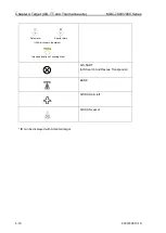
Page 118: ...t with neither reported HDG nor COG Activated target Activated target without HDG Activated target with neither reported HDG nor COG Activated target true scaled outlines Blink in 0 5 sec interval Activated target dangerous targets Blink in 0 5 sec interval Activated target without HDG Blink in 0 5 sec interval Activated target with neither reported HDG nor COG Activated target with heading lines ...

Page 119: ...nal mark East cardinal mark South cardinal mark West cardinal mark Port hand mark Starboard hand mark Isolated danger Safe water Special mark Off position Lights failure Racon failure IALA dictionary topmarks Basic shape Emergency wreck mark North cardinal mark East cardinal mark South cardinal mark West cardinal mark Port hand mark Starboard hand mark Isolated danger ...

Page 120: ... MDC 7000 7900 Series 0093169010 10 4 16 AIS SART AIS Search And Rescue Transponder BASE AIS SAR aircraft AIS SAR vessel ID can be displayed with Activated target Intended location of missing AtoN Safe water Special mark IALA dictionary topmarks ...

Page 121: ...ccur if the picture of the target being tracked is affected by rain snow clutter returns or sea clutter returns or moves very close to land Intensity of echoes and the TT function have a correlation ship and thus the target will be lost if no echoes and detected during six scans in succession If a lost target exists therefore radar gain must be increased to support detection of the target If radar...

Page 122: ...er right of the display is turned orange TT ARPA is effective by using TT in combination with ASSISTANT DISP Manual acquisition 1 Move cursor to a target to be acquired and then press ACQ key A broken circle symbol is displayed at the cursor location and acquisition starts About 30sec from 1min later a broken circle symbol turn into a thick solid line displayed vector of target s motion trend and ...

Page 123: ...TT target selected SELECT ID and DELETE function 1 Press MENU key to display Menu Select TARGET TT SELECT ID select ID number and press ENT key Selection values 1 to 100 2 Select DELETE and press ENT key Cursor operation 1 Move cursor to a TT ARPA target to be deleted keep OFF key pressed and then press ACQ key Delete all TT targets 1 Press MENU key to display Menu Select TARGET TT ALL DELETE and ...

Page 124: ...eference target to calculate own ship speed as ground tracking speed Do not choose a moving target as a reference target A moving produces target error in the vector for TT and AIS which results in wrong collision avoidance information Further an unstable stationary target produces inaccurate speed data and the target itself may become lost The combined use with AIS function cannot be performed Wh...

Page 125: ... be displayed in TGT INFO area at side of the display 3 Move cursor to the REF OFF positon in TGT INFO area at side of the display and OFF characters change to reverse characters Press ENT key to set REF target from TT target GYRO characters in the own ship information area at right side of the display change to yellow Move cursor using Trackball to the GYRO characters then press ENT key GYRO char...

Page 126: ...r target Displayed at indicating numerical value Tracked radar targets dangerous target Red clolor Blink in 0 5 sec interval Lost target Red clolor Pressing OFF key to acknowledge changes of target symbol to normal color and stop blinking ID can be displayed in Tracked target Alarm display and alarm sound disappear by pressing OFF key to acknowledge while color remains red until the target leaves ...

Page 127: ...get is possible and that the accuracy of data is within the specification mentioned below Time of steady state minutes CPA NM TCPA minutes True course Degrees True speed 1 min trend 1 0 3 min prediction 0 3 0 5 5 0 5kn or 1 whichever is greater Preparation Display Range rings as follows By menu 1 Press MENU key to display Menu Select NAV TOOL RR RR ON and press ENT key By trackball 1 Move cursor o...

Page 128: ...appears under the small character x position A test target appears near the direction 10 and range 12NM After approaching to own ship the target moves toward direction 207 Own ship s speed is about 42kn and the test target speed is about 32kn Relative speed is 74kn Turn ON TEST TGT 1 Press MENU key to display Menu Select TARGET TT TEST TGT ON and press ENT key Range scale will change to 12NM autom...

Page 129: ...rackball and move cursor to the target and press ACQ key 2 Confirm appearance of the dotted circle of acquisition start symbol and the parenthesis of value near it The values are indicated in TGT INFO area Note If the parentheses are not displayed then drag a cursor to the acquisition start symbol and press ENT key X 12NM 2NM x 10NM Range ring Cursor x X 12NM 2NM 1 TGT INFO area ...

Page 130: ...isition Confirm that the target has the tracking symbol Confirm that the symbol number is 1 Note If the number is not correct then no comparison with the known result is made Delete the symbol and start it over 2 Compare with the known result after 1 minute from acquisition start 3 Compare with the known result after 3 minutes from acquisition start BRG T 11 7 RNG 8 9NM CTW 207 0 STW 31 5kn CPA 0 ...

Page 131: ...acy is degraded Tracking malfunction RNG Range accuracy is degraded Tracking malfunction CPA CPA accuracy is degraded Tracking malfunction TCPA TCPA accuracy is degraded Tracking malfunction T CRS True course accuracy is degraded Tracking malfunction T SPD True course accuracy is degraded TEST TGT OFF 1 Press MENU key to display Menu Select TARGET TT TEST TGT OFF and press ENT key Stop transmissio...

Page 132: ... NM 2 Turn GAIN RAIN and SEA knobs and set these levels at a minimum 3 Set up the echo alarm as follows Press MENU key to display Menu Select ALARM ECHO ALARM IN and press ENT key Set up the echo alarm range 4 Set up the Guard zone Select ALARM GUARD ZONE ON and press ENT key Set up the range of Guard zone 5 Set up the Auto acquisition Select TARGET AUTO ACQ AREA ON and press ENT key Set up the ra...

Page 133: ...ss STBY TX key and start transmission Then a target appears A target appears near the direction 10 and range 12 NM After approaching to own ship the target moves toward direction 207 Own ship s speed is about 42 kn and the target speed is about 32 kn Relative speed is 74 kn x S Target 12NM 1 Press MENU key to display Menu Select TARGET TT TEST TGT ON and press ENT key Range is fixed at 12 NM and c...

Page 134: ...0 Series 0093169010 10 4 30 Echo alarm 1 Confirm that when the target enters the echo alarm area the echo alarm is displayed in alarm display area at the lower right of the display Press OFF key to acknowledge Then alarm will disappear x Alarm display area X ...

Page 135: ...y acquisition Information of symbol with is displayed in the TGT INFO area CPA TCPA are displayed as missing until tracking is started Move the cursor on symbol and press ENT key if is not displayed yet TGT INFO area 3 Confirm that data is changed from missing after the symbol is changed to tracked one 4 Move the cursor again Delete the tracked symbol by pressing ACQ key while keeping OFF key pres...

Page 136: ...sition 1 If a target enters the Auto acquisition area and 15 seconds pass then automatic acquisition starts Start of tracking is displayed in the alarm display area at lower right of the display Acquired symbol is shown in blinking red until OFF key is pressed to acknowledge Alarm display area X ...

Page 137: ...that the Guard zone alarm is displayed in the alarm display area at the lower right of the display when the tracked symbol has entered the Guard zone Blinking of tracked symbol will stop by pressing OFF key to acknowledge The tracked symbol remains red until it leaves from Guard zone Alarm display area TEST TGT OFF Press MENU key to display Menu Select TARGET TT TEST TGT OFF and press ENT key Stop...

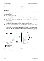
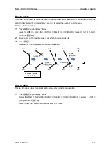
Page 138: ...moving at the present course and speed CRS SPD for the duration set at DELAY vector is displayed in such a way that the own ship is to move at the set CRS T SPD RATE OF TURN and RATE OF SPD from the starting point Note Better information is provided by using relative motion and sea stabilization water tracking The function is terminated once the HDG input SPD input LAT LON input AIS only are disru...

Page 139: ...the cursor OFF and press ENT key TRIAL MANOEUVRE is finished immediately TRIAL OFF When the trial manoeuvre commences count down starts from 300 seconds and ends at 0 second When you decide to stop the function during the countdown select the countdown display and set OFF CRS T This indicates own ship s course after DELAY SPD This indicates own ship s speed after DELAY DELAY This indicates the sta...

Page 140: ...for CRS T SPD RATE OF TURN RATE OF SPD own ship s vector will change when the vector setting is VECT T and the other ship s vector will change when vector setting is VECT REL TRUE VECTOR when own ship s speed is doubled RELATIVE VECTOR when own ship s speed is doubled T VECT T T VECT T T VECT REL T VECT REL ...

Page 141: ...e to guard line from own ship can be set from 0 to 10000m left and right side independently 1 Press MENU key to display Menu Select NAV TOOL GUARD LINE ON and press ENT key 2 Select LEFT set left side distance 0 to 10000m and press ENT key 3 Select RIGHT set right side distance 0 to 10000m and press ENT key Right side guard line Left side guard line Right side distance Left side distance Heading l...

Page 142: ...is no small targets right under the HL marker 1 Press MENU key to display Menu Select NAV TOOL HL BLINK ON and press ENT key 5 3 Stern line STERN LINE is to set up the display of dotted line extended from reference position to bearing scale toward stern direction 1 Press MENU key to display Menu Select NAV TOOL STERN LINE ON and press ENT key Heading line Heading line Stern line ...

Page 143: ...e able to display it on the display 1 Press MENU key to display Menu Select NAV TOOL BARGE ICON BARGE ICON ON and press ENT key 2 Select and set POSITION LENGTH WIDTH LINE NO ROW NO and OFFSET POSITION FWD AFT LENGTH 0m to 511m WIDTH 0m to 511m LINE NO 1 to 10 ROW NO 1 to 10 OFFSET 0m to 511m Length Width Line number Row number Offset OS outline Barge icon OS outline Forward positon After position...

Page 144: ... This page intentionally left blank ...

Page 145: ... clear operation color setting and line style for each block and set up recording interval common to all blocks Record Display of Own ship past track is set for each block 1 Press MENU key to display Menu Select MAP OWN TRACK select 0 to 9 select OFF ON or DISP and press ENT key Setting Record Display of Own ship past track OFF Own ship past track is not recorded Own ship past track is not display...

Page 146: ...ress the ENT key You can easily change it when you set OS PAST TRK REC function to the function key Refer to 2 21 Function key usage 2 Select PLOT INT and press ENT key after selecting the set up value Selection values 1sec 2sec 5sec 10sec 30sec 1min 3min 3 Select STYLE select BLOCK NUMBER 0 to 9 select COLOR select color from eight colors press ENT key PAST TRACK of the selected block will turn s...

Page 147: ...t STYLE select style press ENT key 7 Select PLOT INT and press ENT key after selecting the set up value Selection values OFF 2sec 15sec 30sec 1min 3min 5min 8 Select PLOT NUMBER and press ENT key after selecting the set up value Selection values 50 100 200 500 1000 Target track start 1 Move cursor to an AIS target or TT ARPA target to display track keep ENT key pressed and then press ACQ key Targe...

Page 148: ... Don t display coast line EDIT Create coast line CURSOR BLOCK NUMBER MOVE Change the position CURSOR BLOCK NUMBER ADD Insert a position data CURSOR BLOCK NUMBER DELETE Delete a position data CURSOR BLOCK NUMBER CLEAR Clear a selected block number coast line data How to edit 1 CURSOR OPERATION 1 Press MENU key to display Menu Select MAP COAST LINE EDIT CURSOR select 1 to 10 GO and press ENT key 2 M...

Page 149: ...is displayed 2 Select LAT Latitude data set screen is displayed Set LAT data by moving of trackball to the right left up or down and press ENT key 3 Select LON Longitude data set screen is displayed Set LON data by moving of trackball to the right left up or down and press ENT key 4 Select COLOR Eight colors box is displayed Select color by moving of trackball up or down and press ENT key 5 Select...

Page 150: ... mark will be displayed on the selected coast line and numerical data is shown at coast line info area 3 Move cursor to new position then press ENT key 4 Press MENU key to exit MOVE operation 2 BLOCK NUMBER OPERATION 1 Press MENU key to display Menu Select MAP COAST LINE MOVE BLOCK NUMBER select 1 to 10 Following input menu is displayed 2 Select NUMBER NUMBER data screen is displayed select 1 to 1...

Page 151: ...le mark will be displayed on the selected 3 Move cursor to the position that new data will be added then press ENT key 4 Press MENU key to exit ADD operation 2 BLOCK NUMBER OPERATION 1 Press MENU key to display Menu Select MAP COAST LINE ADD BLOCK NUMBER select 1 to 10 Following input menu is displayed 2 Select NUMBER NUMBER data screen is displayed select 1 to 100 Press ENT key Selected number s ...

Page 152: ... Press ENT key Selected coast line data will be deleted 2 BLOCK NUMBER OPERATION 1 Press MENU key to display Menu Select MAP COAST LINE DELETE BLOCK NUMBER select 1 to 10 Following delete menu is displayed 2 Select NUMBER NUMBER data screen is displayed select 1 to 100 Press ENT key Selected number s numerical data is shown 3 Select SET and press ENT key to delete selected data How to clear All da...

Page 153: ...arm function for NAV LINE CROSS alarm Refer to 3 4 Nav line cross 1 Press MENU key to display Menu Select MAP NAV LINE NAV LINE Select the number of the nav line to display ALL 1 to 10 OFF EDIT Make nav line CURSOR BLOCK NUMBER MOVE Revise the position of the nav line CURSOR BLOCK NUMBER ADD Add a point data in a nav line CURSOR BLOCK NUMBER DELETE Delete a point data in a nav line CURSOR BLOCK NU...

Page 154: ...nu is set to OFF then route waypoint name information will not be displayed and if set to ON all waypoints on the route will have name information displayed next to them 1 Press MENU key to display Menu Select MAP ROUTE ROUTE Select the number of the route to display ALL 1 to 10 OFF EDIT Make route CURSOR BLOCK NUMBER MOVE Revise route position CURSOR BLOCK NUMBER ADD Add a point to a route CURSOR...

Page 155: ...to delete event mark using cursor and ENT key or BLOCK NUMBER CLEAR Clear all event marks in a given memory block User can designate function key such as F1 F6 to EVENT CURSOR or EVENT OWN for quick shortcut to input EVENT MKR Refer to 2 21 Function key usage When set EVENT MKR by using function key operation this radar can output Lat Lon data of EVENT MKR to external device It is necessary to set...

Page 156: ...nts in area CURSOR BLOCK NUMBER ADD Add a point to any given position in an area line CURSOR BLOCK NUMBER DELETE Delete a point data in area CURSOR BLOCK NUMBER CLEAR Clear selected block number area data AREA operation is same as 3 2 Map area alarm operation 6 9 MONITORED ROUTE This function when activated can display ROUTE information from external device such as chart plotter or GPS navigator R...

Page 157: ...t TARGET TRACK ID and the numbers will disappear or reappear with turning this function on or off 1 Press MENU key to display Menu Select MAP TARGET TARCK ID ON and press ENT key 6 12 DATUM Local geodetic datum and datum offsets from a reference datum This is used to define the datum to which a position location and geographic locations are referenced Latitude Longitude and altitude offsets from t...

Page 158: ...ach letter when finished select EXIT and press ENT key The three letters of 999 in the DATUM menu change to the edited letters 6 14 POSITION OFFSET This is to select OFFSET input of position Selection values DTM MAN 1 Press MENU key to display Menu Select MAP OFFSET select DTM or MAN and press ENT key POSITION MANUAL OFFSET LAT LON position offset values input is available only when MAN of POSITIO...

Page 159: ...d with straight lines Under each buoy symbol water temperature can be indicated The latest data will be indicated with marked out symbols and ID can be also indicated at the right hand side of the symbol as shown in the above examples 1 NUM DISP This is the function to display Buoy IDs at the right sides of the latest data buoy symbols 2 WAT TEMP DISP This is the function to display water temperat...

Page 160: ...ENU key to display Menu Select MAP LAT LON LINE select ON or OFF and press ENT key 6 18 C MAP chart display This radar can display chart of C MAP The CHART and CHART DISP SET menu are displayed when C MAP chart of SD card type has been inserted in the lower card reader on the rear of the Display unit CAUTION Please ensure that the C MAP SD card must be inserted in the lower card reader on the rear...

Page 161: ...C LOCAL time can be changed directly at the upper right of the own ship data area with trackball and ENT key without using menu Note Refer to MAINTENANCE I O TIME menu for detailed how to set time For display of DATE TIME receive ZDA sentence from the external device or set the internal clock of radar Refer to 4 2 1 Setup TIME of Installation manual When the battery runs low the internal clock of ...

Page 162: ... so no action is required from user to save settings Edit User Name The used user memory s name can be changed by next operation 1 Press MENU key to display Menu Select SYSTEM USER EDIT USER NAME 2 Edit user name window will appear and can change user name Maximum 10 letters or numbers can be set for the name After name has been changed press ENT key to save setting Default User setting Using thes...

Page 163: ... 8 and press ENT key Selection values 1 to 8 1 Lowest frequency 8 Highest frequency Key click ON OFF 1 Press MENU key to display Menu Select SYSTEM SOUND KEY CLICK select ON or OFF and press ENT key External buzzer setting External buzzer signal Failure alarm can be output from J1 connector on the back panel Output signal is relay contact Alarm contact will close in case of failure Output of relay...

Page 164: ...release the RANGE key Language changes to Japanese To English 1 Press POWER ON OFF key to turn on while keeping RANGE key 2 Keep RANGE key pressed until the start up screen is displayed then release the RANGE key Language changes to English 7 6 DISPLAY INFOMATION DISP INFO This radar can reduce the radar information items to watch radar image wider Selection items are ALL MAIN OFF the indication i...

Page 165: ... ALARM and MAP 1 Press MENU key to display Menu Select SYSTEM HELP select ON or OFF and press ENT key 7 8 MAINTENANCE MENU STARTUP Refer to 4 2_STARTUP menu of Installation manual I O Refer to 4 3_Setup I O Interface of Installation manual SECTOR MUTE Refer to 4 4_Setup SECTOR MUTE mode of Installation manual PRESET Refer to 4 5_Setup PRESET of Installation manual BACKUP BITE Refer to Chapter 9_Si...

Page 166: ...TENANCE BACKUP SETUP LOAD GO and press ENT key External save of setup and map data To save setup and map data externally this information can be later used to restore after a possible malfunction The external memory uses an SD memory card CAUTION Please do not use the SD memory card which is loaded with software program files To perform external backup to SD card 1 Insert SD memory card in the upp...

Page 167: ...used while transmitting TOTAL HOUR menu indicates the total operating time of the radar This menu can reset total hour to 0 1 Press MENU key to display Menu Select MAINTENANCE TOTAL HOUR RESET and press ENT key TX HOUR menu indicates the total transmitting time of the radar This is useful information to use when exchanging radar parts Use this hour information to judge magnetron life expectancy Re...

Page 168: ...NTENANCE MENU SETUP GO and press ENT key Setup menu display will display 2 Select menu item to set ON or OFF select X or and press ENT key 3 When setup finish press MENU key Menu display will disappear Press MENU key again X mark menu items are not displayed When set ECHO to x all ECHO menu items will not be available ECHO ECHO PICTURE MODE IR OFF PROCESS VIDEO CONTRAST 3 EXPANSION NOISE REJ OFF I...

Page 169: ...upper card reader on the rear of the Display unit 4 Press POWER ON OFF key to turn on radar will start update procedure automatically Message of LOADING IN PROGRESS PLEASE DO NOT POWER OFF etc and time bar will be displayed During updating EBL1 and VRM1 EBL2 and VRM2 BRILL and PANEL key s lamps flash red Few minutes later when program update is complete LOADING COMPLETE and PLEASE EJECT SD CARD me...

Page 170: ... This page intentionally left blank ...

Page 171: ...a glance The microwave radiated from the radar is referred to as pulse wave and the transmitting and receiving of these waves is alternated Up to thousands of pulse waves are transmitted and received during one rotation The typical radar antenna is of parabolic type or slotted array type and its performance is essential for good radar performance Some of factors affecting the quality of the target...

Page 172: ...h h1 Characteristics of radar radio wave D NM h2 Target height m h1 Antenna height m Target hardness reflected The strength of the reflected wave from a target varies depending on not only the distance from the target its height or size but also its material and features A target with a low degree of reflection or low incident angle such as FRP Fiber Reinforced Plastic and wooden ship is not refle...

Page 173: ...ion should be paid in shadowed areas False image An image that does not actually exist false image at sea may appear on the display The phenomena that causes false echoes are categorized and be described as follows Virtual image The image of a large physical object in proximity may appear in two different orientations One is a real image and the other is a false image caused by wave re reflected b...

Page 174: ...ring between own ship and the reflective target changes then the duplicate targets will disappear Therefore this false image can be easily distinguished Double image Real image False image caused by double image Own ship Large vessel Side lobe images The microwave beam radiated from the antenna has a side lobe in different direction than that of the main beam Since this side lobe level is lower th...

Page 175: ...splayed as a false image with closer distance than the actual one This phenomenon is a result of the wide range echo delay time exceeding the transmission period and is displayed as echo in the following rotation If the range scale is changed and the target range is changed it can be judged as a false image 8 3 Radar interference When the radar with the same frequency band is used nearby interfere...

Page 176: ... This page intentionally left blank ...

Page 177: ...o alarm sound ALARM TEST 9 2 Operation unit panel key is not operational PANEL TEST 9 3 TT ARPA is not operational DIAGNOSE TT 9 4 No AIS display DIAGNOSE AIS 9 5 Need to confirm serial input SERIAL MONITOR 9 6 No radar video display ANT MONITOR 9 7 Frozen display 9 8 About alarms 1 Press MENU key to display Menu Select MAINTENANCE BITE MAINTENANCE BITE ALARM TEST PANEL TEST DIAGNOSE TT DIAGNOSE A...

Page 178: ...frequency setting because it may be hard to hear the alarm sound according to the setting value Select SYSTEM SOUND FREQUENCY Initial setting 4 3 Alarm sounds two times and alarm display appears at the lower right of the display Alarms displayed are WARNING B 999 Test alert only 4 Confirmation is completed if alarm sounded 5 Alarm sounds are repeated every 60 seconds Select MAINTENANCE BITE ALARM ...

Page 179: ... display Menu Select MAINTENANCE BITE PANEL TEST 2 Panel illustration will appear on the display 3 Press any key except MENU key mark will appear at the left side of key name during the key press The line in the circle will rotate when the knob is turned The circle color will change when the knob is pressed The small circle in the square will move when trackball is moved 4 Pressing MENU key will c...

Page 180: ...y being pressed First confirm that INPUT RNG is properly set The targets outside of INPUT RNG will not be acquired This procedure confirms ATA function 1 Press MENU key to display Menu Select MAINTENANCE BITE DIAGNOSE TT 2 Confirm mark appears on the left side of HDG 3 Turn trackball to the left to complete If x mark is displayed in step 2 then confirm HDG input for Display unit ...

Page 181: ... If x mark is displayed in step 2 then In the case of AIS DATA No valid AIS data input Confirm AIS receiver connected to Display unit AIS DATA is usually input to AIS J2 connector In the case of HDG No valid HDG input Confirm HDG input of Display unit HDG is usually input to GYRO connector In the case of SPD No valid SPD input Confirm SPD input of Display unit SPD is usually input to SDME J6 conne...

Page 182: ...OP2 AIS or ALL and press ENT key OP1 and OP2 port will be effective when JB 35 is connected to J3 ALL can confirm the data of all ports at a time 2 Input data will be displayed Since the data keeps coming in and the display keeps changing it may be hard to observe the sentences By pressing ENT key data display will stop temporarily to confirm data content 3 Turn trackball to left to complete Data ...

Page 183: ...ball to left to complete Antenna status criteria in step 2 Connected scanner model name and type HIGH VOLTAGE If the value is other than xxx to xxx indicates high voltage malfunction MAG CURRENT MONI If the value is other than xx to xxx indicates magnetron malfunction MAG HEATER If the value is other than xx to xxx indicates magnetron malfunction MOTOR MONI TUNE VOLTAGE If the value is other than ...

Page 184: ...ight pattern triangle icons These icons will change every two seconds three angles of directions turn to the clockwise When this movement stopped radar system will be stopping Restart Display unit immediately Frozen Display refers to case when video is not refreshed or cursor is not responsive 1 Turn GAIN SEA and RAIN knob to confirm changes of video Echo 2 Turn trackball to confirm if cursor is m...

Page 185: ...ight of the display Abnormalities are categorized as Alarm Warning and Caution When alarm display actually appears and there is something wrong with radar record the alarm details by type location and status and press OFF key The alarm sound and display will disappear Multiple errors may be displayed one by one Record all alarms and press OFF key for every alarm The type of Alarm Warning and Cauti...

Page 186: ...ed the CPA TCPA limit Tracked target has turned into dangerous target A A 191 2 8 AIS target exceeded the CPA TCPA limit AIS target has turned into dangerous target A W 192 1 4 Tracked target entered into the guard zone Tracked target has entered into the guard zone A W 192 2 5 Auto acquisition of a radar target Captured a target entered into auto acquisition area A W 192 3 9 AIS target entered in...

Page 187: ... C 194 25 109 AIS no data There is no AIS data VDM is not input from AIS B C 194 26 110 SPD is unavailable VBW VTG RMA or RMC are not inputted B C 194 27 111 COG SOG is unavailable COG SOG is not inputted B W 999 1 89 Test alert only Under alert test A W 10000 1 53 Echo area alarm detected Images are detected in echo alarm area A W 10000 2 15 Echo map area alarm detected Images were detected in ma...

Page 188: ...ormality is input in AIS alarm terminal of AIS port or the terminals are open B C 16000 3 66 No WGS84 DATUM Input geodetic system is not WGS84 A A 17000 1 41 Antenna not connected Connector of Antenna may not be connected to Antenna or Scanner unit may be faulty A A 17000 2 42 Antenna magnetron current abnormal Magnetron may be at the end of life or transmission high voltage fuse blown A A 17000 3...

Page 189: ... error Flash memory erase error B W 18001 3 39 Flash memory write error Flash memory write error B W 18001 4 40 Flash memory checksum error Flash memory checksum error B C 18002 1 71 SD card problem SD card may be broken B C 18002 2 72 SD card not ready There is not SD card B C 18002 3 73 SD card write protected SD card is protect mode B C 18002 4 74 SD card not enough free space Memory of SD card...

Page 190: ... operating distance set for targets Pre heating Operated transmission key during pre heating countdown No HDG LAT LON signal As signals of ship s bearing latitude longitude had not been input functions that need those signals have been disabled No HDG signal As signals of ship s bearing had not been input functions that need ship s bearing signal were disabled No SPD signal As speed signal had not...

Page 191: ...d the reference Tracking malfunction T SPD AS the result of TT test the accuracy of true speed has exceeded the reference Time to trial manoeuvre is less than 30 seconds The remaining time of trial manoeuvre is less than 30 seconds Reference target overload Attempted to acquire reference target beyond 3 Do not use MAN COG SOG Cannot use AIS with COG SOG data inputted by manual Do not use REF COG S...

Page 192: ... This page intentionally left blank ...

Page 193: ... 7910 MDC 7020 7920 Scanner unit RB717A RB718A RB719A Rotation 24 rpm or 48 rpm Output frequency X band 9410MHz 30MHz Output power Peak 6 kW 12 kW 25 kW Magnetron MSF1422B MSF1425B M1458A Temperature 25 C to 55 C Water protection IPX6 Range PRF Pulse width 0 125 0 25 0 5 0 75 1 5 3 6 12 24 32 48 64 96 2500 0 08 2000 0 08 2500 0 08 2000 0 08 2000 0 25 1300 0 3 2000 0 25 1300 0 3 1000 0 5 800 0 6 70...

Page 194: ...125 0 25 0 5 0 75 1 5 3 6 12 24 32 48 64 96 NM 32 NM 64 NM is for 6kW 12kW only Initial value 96 NM is for 25kW only Initial value Bearing accuracy 1 Presentation modes Head up North up and Course up Functions CFAR Clutter rejection Interference rejection Expansion Process Residual image Averaging VRM EBL Parallel index ERBL Cursor position Lat Lon Bearing true relative Trail true relative Own shi...

Page 195: ...MDC 7000 7900 Series Chapter 10 Specifications 0093169010 10 10 3 10 3 External view and dimensions Unit mm inch MRD 108 MRO 108 MRM 108 ...

Page 196: ...Chapter 10 Specifications MDC 7000 7900 Series 0093169010 10 10 4 Unit mm inch RB717A RB718A RB719A 9Feet RW701B 09 For RB718A only ...

Page 197: ...10 11 12 13 14 15 CLEAR CANCEL GO RANGE KEEP OFF ON FIRST IMPRESSION OFF 30sec 1min 3min 6min 12min 30min 60min MARK 0 to 1440 min DITHER OFF ON DISPLAY DISPLAY CENTER ANT CCRP ANT POSN OFF ON OFF CENT POINT CURSOR OPPOSITE STAB MODE SEA GND TM RESET C UP RESET RANGE UNIT NM km sm kf ky ROTATION MARGIN 0 0 to 30 0o ROTATION SPEED FAST MEDIUM SLOW ALL PPI OFF ON FERRY MODE FERRY MODE OFF ON HDG 0o ...

Page 198: ...8 colors DIVIDE OFF ON SET ADD CURSOR 1 to 10 CANCEL GO BLOCK NUMBER 1 to 10 NUMBER 1 to 100 LAT 90o 00 000S to 90o 00 000N LON 180o 00 000W to 180o 00 000E COLOR 8 colors DIVIDE OFF ON SET DELETE CURSOR 1 to 10 CANCEL GO BLOCK NUMBER 1 to 10 NUMBER 1 to 100 LAT 90o 00 000S to 90o 00 000N LON 180o 00 000W to 180o 00 000E SET CLEAR BLOCK NUMBER 1 to 10 CANCEL GO DETECT LEVEL 1 2 3 4 5 6 7 8 9 10 11...

Page 199: ... 1 to 10 CANCEL GO LIST HISTORY LIST HISTORY LIST SORT PRIORITY ALL ALARMS WARNINGS CAUTIONS CATEGORY ALL A B TIME LAST IN FIRST IN ALARM ON OFF TT AUTO ACQ OFF ON LOST OFF ON CPA TCPA OFF ON AIS AUTO ACQ OFF ON MESSAGE OFF ON LOST OFF ON CPA TCPA OFF ON WITHOUT HDG COG OFF ON I O HDG INPUT OFF ON SPD INPUT OFF ON LAT LON INPUT OFF ON WPT ARRIVAL OFF ON TARGET VECT TRUE REL TRUE REL TIME OFF 30sec...

Page 200: ...W MEDIUM FAST AIS FILTER CLASS A OFF ON CLASS B OFF ON RNG 0 0 to 64 0 NM SPD 0 0 to 100 0 kn CPA TCPA OFF ON MOORED OFF ON AT ANCHOR OFF ON AGROUND OFF ON NUC OFF ON GUARD ZONE OFF ON ECHO ALARM OFF ON AIS ALARM SLEEPING LOST OFF ON WITHOUT HDG COG OFF ON TT TT OFF ON SELECT ID 1 to 100 DELETE SHAPE EDIT LABEL 10 words ANCH ACQ ALL DELETE REF ACQ TEST TGT OFF ON TGT LEVEL 1 2 3 4 5 6 7 8 9 10 11 ...

Page 201: ...P OUTLINE SHIP OUTLINE OFF ON CCRP 1 to 4 OS PROFILE HL BLINK OFF ON STERN LINE OFF ON BARGE ICON BARGE ICON OFF ON POSITION FWD AFT LENGTH 0 to 511 m WIDTH 0 to 511 m LINE NO 1 to 10 ROW NO 1 to 10 OFFSET 0 to 511 m MAP OWN TRACK 0 OFF ON DISP 1 OFF ON DISP 2 OFF ON DISP 3 OFF ON DISP 4 OFF ON DISP 5 OFF ON DISP 6 OFF ON DISP 7 OFF ON DISP 8 OFF ON DISP 9 OFF ON DISP PLOT INT 1sec 2sec 5sec 10sec...

Page 202: ... BLOCK NUMBER 1 to 10 NUMBER 1 to 100 LAT 90 00 000S to 90 00 000N LON 180 00 000W to 180 00 000E COLOR 8 colors DIVIDE OFF ON SET DELETE CURSOR 1 to 10 CANCEL GO BLOCK NUMBER 1 to 10 NUMBER 1 to 100 LAT 90 00 000S to 90 00 000N LON SET CLEAR BLOCK NUMBER 1 to 10 CANCEL GO NAV LINE NAV LINE ALL 1 2 3 4 5 6 7 8 9 10 OFF EDIT Same COAST LINE EDIT MOVE Same COAST LINE MOVE ADD Same COAST LINE ADD DEL...

Page 203: ...CLEAR CANCEL GO BLOCK DATA WPT FLAG OFF ON LAT LON LINE OFF ON CHART OFF ON CHART DISP SET LAND FILL OFF ON PLACE NAME OFF ON LIGHTHOUSE OFF ON BUOY OFF ON FISH HAVEN WRECK OFF ON TRAFFIC ROUTES OFF ON CAUTION AREA OFF ON FISHERY OFF ON CABLE OFF ON DEPTH CON BRILL ECHO WHITE YELLOW GREEN MULTI USER1 USER2 TRAIL BLUE BROWN USER1 USER2 BKGND PPI BLACK BLUE USER1 USER2 BKGND DATA BLACK BLUE USER1 US...

Page 204: ... TRK Set 8 colors individually MONITORED ROUTE LAT LON LINE GPS BUOY CURSOR Set 3 colors of LOW MIDDLE and HIGH CHART LAND DEPTH ECHO 20 to 100 TRAIL 20 to 100 BKGND 20 to 100 OS TOOL 20 to 100 TGT 20 to 100 MAP 20 to 100 CURSOR 20 to 100 DATA 20 to 100 MENU ALERT 20 to 100 RESET CANCEL GO SYSTEM INTER SWITCH INDEPENDENT MASTER INDEPENDENT SLAVE DUAL MASTER DUAL SLAVE CROSS MONITOR TIME UTC LOCAL ...

Page 205: ...L T REL TRAIL TIME TRAIL RESET DISPLAY STAB MODE TM RESET C UP RESET FERRY MODE ALARM TARGET VECT T REL VECT TIME CPA TCPA AIS TT DELETE ACQ TT REF ACQ ANCH TRUE ANCH REL NAV TOOL RR BRG T REL GUARD LINE SHIP OUTLINE STERN LINE BARGE ICON MAP OWN TRACK MAP DISP CHART TLL OUT SYSTEM TIME TGT LIST SORT OS PAST TRK REC EVENT CURSOR EVENT OWN ASSISTANT DISP PAST POSN T REL PAST POSN TIME AUTO ACQ AREA...

Page 206: ... OFF ON 80 OFF ON 96 OFF ON OFF ON OFF ON OFF ON TIMES ENABLE 30sec OFF ON 1min OFF ON 2min OFF ON 3min OFF ON 5min OFF ON 6min OFF ON 10min OFF ON 12min OFF ON 15min OFF ON 24min OFF ON 30min OFF ON 45min OFF ON 48min OFF ON 60min OFF ON 2hr OFF ON 4hr OFF ON 8hr OFF ON 16hr OFF ON 24hr OFF ON LOGO LOGO OFF WAIT STANDBY LOAD CANCEL GO MOTOR HIGH SPEED OFF Setting RANGE 0 0625 to 144 NM MOUSE SPEE...

Page 207: ...MAN 1 000W to 1 000E XXXX POSITION input source display OFFSET DATUM REF LOCAL SET DRIFT SET DRIFT VDR MAN SET MAN 0 0 to 359 9 DRIFT MAN 0 0 to 100 0 kn XXX TIME TIME ZDA CLOCK TIME ZONE 14 30 to 14 30 CLOCK SET DATE DD MM YY TIME 00 00 to 23 59 XXXX TIME input source display TIME ZONE OUTPUT OUTPUT J3 DTM 0 0 to 10 0sec OUTPUT J5 EVE 0 0 to 10 0sec OUTPUT J6 GLL 0 0 to 10 0sec OUTPUT OP1 HBT 0 0...

Page 208: ...N MAX 0 to 4095 SEA MIN 0 to 4095 SEA MAX 0 to 4095 GAIN MIN 0 to 4095 GAIN MAX 0 to 4095 GAIN OFFSET 0 to 4095 SEA OFFSET 0 to 4095 BACKUP SETUP LOAD CANCEL GO SETUP SAVE CANCEL GO SD CARD SETUP LOAD CANCEL GO SETUP SAVE CANCEL GO MARK LOAD CANCEL GO MARK SAVE CANCEL GO TGT TRACK LOAD CANCEL GO TGT TRACK SAVE CANCEL GO OWN TRACK LOAD CANCEL GO OWN TRACK SAVE CANCEL GO PARAMETER RESET CANCEL GO MA...

Page 209: ...erence point position 2 OFF key ACQ key Move cursor to a TT ARPA target to be deleted And press ACQ key while pressing OFF key Delete TT target Refer to 4 3 TT ARPA Delete TT target 3 OFF key Function key which EVENT CURSOR function is registered with F1 F2 F3 F4 F5 or F6 Move cursor to an event mark to be deleted And press Function key while pressing OFF key Delete event mark Refer to 6 7 EVENT M...

Page 210: ...nction key is displayed Refer to 2 21 Function key usage 2 Move cursor to AIS or TT ARPA target to display track And press ACQ key while pressing ENT key Start target track Refer to 6 3 Target track past position display 3 Move cursor to AIS or TT ARPA target to track off and press OFF key Finish target track Refer to 6 3 Target track past position display 4 MENU ENT key Power ON Long press After ...

Page 211: ...ng true T hh CR LF Check sum Heading degrees true Note for IMO mode II IN HE HN HC GA GP GL GN and SN are accepted HDG Heading deviation and variation hh CR LF Check sum Magnetic variation degrees Magnetic variation degrees Magnetic sensor heading degrees Note This sentence is not accepted for IMO radar HDM Heading Magnetic M hh CR LF Check sum Heading degrees magnetic Note This sentence is not ac...

Page 212: ...hhmmss ss A llll ll N S yyyyy yy E W Speed VBW Dual ground water speed A hh CR LF Check sum These fields are not used Status ground speed A Valid V Invalid Transverse ground speed knots Longitudinal ground speed knots Status w ater speed A Valid Invalid Tranverse w aterspeed knots Longitudinal w ater speed knots Note for IMO mode II IN VD GA GP GL GN SN VM and VW are accepted VTG Course over groun...

Page 213: ...itude Check sum UTC of position These field is not used GPS quality indicator 1 2 3 4 5 Valid 0 6 7 8 Invalid 0 Fixnot invalid or invalid 1 GPS SPS mode 5 Float RTK 2 Differential GPS SPS mode 6 Estimated mode Note for IMO mode 3 GPS PPS mode 7 Manual input mode II IN GA GP GL GN and SN are accepted 4 Real time Kinematic 8 Simulator mode hh CR LF a GGA hhmmss ss llll ll N S yyyyy yy E W a xxxx xx ...

Page 214: ...ific GNSS data a hh CR LF UTC of Not used Check sum position fix Longitude E W Navigation status S Safe Latitude N S Mode indicator C Caution Status A Valid V Invalid A D P R F Valid U Unsafe E M S N Invalid V Not valid RMA Recommended minimum specific LORAN C data a hh CR LF Not used Not used Check sum Longitude degrees E W Mode indicator A D valid Latitude degrees N S E M S N invalid Status A da...

Page 215: ...ert entries Sequential message identifier 00 to 99 Sentence number 01 to 99 Total number of sentences for this message 01 to 99 ARC Alert command refused c hh CR LF Relese time Check sum Note Refused alert command A Q O or S A Acknowledge Alert instance 1 to 999999 Q Request repeat information Alert identifier O Responsibilitytransfer Manufacturer mnemonic code S Silence ALR Set alarm state Time o...

Page 216: ...F data link message x hh CR LF Check sum Number of fill bits 0 to 5 Encapsulated ITU R M 1371 radio message Message part 6bit fields AIS channel A B Message number 1 to 9 Sentence number 1 to 9 Total number of sentences needed to transfer the message 1 to 9 VDO AIS VHF data link own vessel report x hh CR LF Check sum Number of fill bits 0 to 5 Encapsulated ITU R M 1371 radio message Message part 6...

Page 217: ...on latitude longitiude Mode indicator N S E W Waypoint ID Distance nautical miles Note Mode indicator Bearing digrees magnetic A D Valid Bearing digrees true E M S N Invalid RTE Routes hh CR LF Check sum w aypoint n identifier Additional w aypoint identifiers Waypoint identifire FROM TO Route identifier Message mode C complete route all w aypoints W w orking route first listed w aypoint is FROM se...

Page 218: ...g digrees true E M S N Invalid x x N c c yyyyy yy E W x x T x x M BWC hhmmss ss llll ll N S yyyyy yy E W x x x x x x A RMB A x x a c c c c llll ll N S RMB Recommended minimum navigation information a hh CR LF Status Not used Destination Not used Check sum A Valid w aypoint longitude Mode indicator V Data Direction E W A D valid Invalid to steer Destination w aypoint E M S N invalid L R latitude N ...

Page 219: ... Total number of sentences WPL Waypoint location hh CR LF Check sum Waypoint identifier Waypoint longitude E W Waypoint latitude N S c c WPL llll ll N S yyyyy yy E W c c a c c c c c c RTE x x x x Depth DPT Depth Check sum Maximum range scale in use Offset from transducer in metres Water depth relative to the transducer in metres DBT Depth below transducer Check sum Water depth fathoms Water depth ...

Page 220: ...tus These fields are not used status status status status status A Valid B Blink w arning Note When only tw o TD data are effective TD data is displayed C Cycle w arning S SNR w arning a hh CR LF x x a x x a x x a x x a x x a GLC xxxx x x Wind MWD Wind direction and speed hh CR LF Check sum Wind speed m s Wind speed knots Wind direction 0 to 359 magnetic Wind direction 0 to 359 true MWD x x T x x ...

Page 221: ...ransfer the message 01 to FF TLB Target label hh CR LF Check sum Additional label pairs x x c c Label assigned to target n Target number n reported by the device TTM Tracked target message hh CR LF Target Target Target UTC Check sum distance course label Reference Type of from degrees Speed target R acquisition ow n ship true distance null otherw ise A Automatic Target number Target speed units N ...

Page 222: ...e Unacknow ledge Note Alert priority S Active Silenced E Emergency Alerm for use w ith Bridge Alert Management A Active Acknow ledge or active A Alarm O Active Responsibility transferred W Warning U Rectified Unacknow ledge C Caution N Normal ALF x x x hhmmss ss a a a aaa x x x x x x x c c hh CR LF 11 5 Details of the radar data output Data standard name IEC61162 1 or IEC61162 2 Own ship data and ...

Page 223: ...cturer mnemonic code S Silence ALR Set alarm state Time of alarm Check sum condition Alarm s description text change UTC Alarm s acknow ledge state A acknow ledged V unacknow ledged Alarm condition A threshold exceeded V not exceeded Unique alarm number identifier at alarm source ACN Alert command a hh CR LF Relese time Check sum Sentence status flag C Alert command A Q O or S Note Alert command A...

Page 224: ...n sentence x hh CR LF Check sum Sequential sentence identifier Equipment status A Yes V No Configured repeat interval HBT x x A Activity information EVE General event message c c hh CR LF Check sum Event description Tag code used for identification of source of event Event time EVE hhmmss ss c c ...

Page 225: ...1 or IEC 61162 2 is transmittable Circuit configuration RS422 driver IC Type SN65HVD3085 TI Serial data output circuit OUT B Data output OUT A SN65HVD3085 J3 and J5 Data connector pin assignment Display unit upper view J3 and J5 Pin number Signal name 1 Shield 2 OUT A 3 OUT B 4 IN A 5 IN B 6 12V Data connector pin assignment 1 2 3 4 5 6 Input connector J3 and J5 Connector used BD 06PMMP LC7001 Con...

Page 226: ...type signal conforming to IEC61162 1 or IEC 61162 2 is transmittable Circuit configuration RS422 driver IC Type SN65HVD3085 TI Serial data output circuit OUT B Data output OUT A SN65HVD3085 J6 Data connector pin assignment Display unit upper view J6 Pin number Signal name 1 Shield 2 OUT A 3 OUT B 4 IN A 5 IN B 6 NC Data connector pin assignment 1 2 3 4 5 6 Input connector J6 Connector used BD 06PM...

Page 227: ...3 981 kHz Negative 1 037 μs TTL 200 Ω Vertical sync signal V SYNC 60 0 Hz Negative 47 μs TTL 200 Ω R G B Video signal Positive 0 7 V p p 75 Ω Alarm output Contact Capacity 1A Alarm contact will close in case of failure Pin number Signal name 1 RVD 2 R GND 3 GVD 4 G GND 5 BVD 6 B GND 7 H SYNC 8 V SYNC 9 ALARM 10 ALARM J1 External monitor and alarm output connector pin assignment Display unit upper ...

Page 228: ... acceptable BD 08BFFA LL6001 Serial data input Listener Standard signals conforming to IEC61162 2 is acceptable Input load 500 Ohm Circuit configuration Photo coupler Type ACPL M61 Avago Serial data output circuit Talker Standard signals conforming to IEC61162 2 can be output Circuit configuration RS422 Driver Receiver IC Type SN65HVD3085 TI Separated from ground level 1 2 3 4 7 8 5 6 J2 Data conn...

Page 229: ...ch J8 Connector used BU 12PMMP LC7001 Connector acceptable BU 12BFFA LL7001 Pin number Signal name 1 VIDEO OUT 2 TRIG OUT 3 GND 4 AZIP OUT 5 SHF OUT 6 GND 7 VIDEO IN 8 TRIG IN 9 GND 10 AZIP IN 11 SHF IN 12 12VDC Data connector pin assignment 1 2 3 4 5 6 7 8 9 12 10 11 J8 Inter switch connector pin assignment Display unit upper view ...

Page 230: ...pass magnetic HC HC gyro north seeking HE GYRO gyro non north seeking HN GYRO Integrated instrumentation I I INS Integrated navigation IN INS Loran C LC LC Electronic positioning system SN EPFS Velocity sensors Doppler general VD DLOG magnetic log VM LOG mechanical log VW LOG Other devices Display of talker device 11 5 7 Priority of talker device code Heading II IN HE HN HC GN GP GL GA SN Speed II...

Page 231: ...RD VIEW 2 56 Brightness 2 34 Brilliance 2 2 C C UP 2 15 CAUTION 1 7 CCRP 2 51 CFAR 2 11 COAST LINE 6 4 Course up 2 15 CPA TCPA 4 3 CROSS 2 49 Cursor 2 22 2 50 Cursor Access 1 12 Cursor data 2 50 D DATUM 6 13 Day Night 2 32 Delete all TT target 4 19 Delete TT target 4 19 Display center 2 51 Display Mode 2 14 DUAL MASTER 2 49 DUAL SLAVE 2 49 E EBL 2 23 EBL OFFSET 2 24 Echo alarm 3 1 Echo color 2 32 ...

Page 232: ...uisition 4 18 MAP 6 1 Map area 3 3 MENU 1 11 MMSI 4 11 MONITOR 2 49 MONITORED ROUTE 6 12 N N UP 2 16 NAV LINE 6 9 Nav line cross 3 8 Noise rejection 2 44 North up 2 16 O Off Center 2 38 Own ship outline 2 53 OWN SHIP PAST TRACK 6 1 Own ship profile 2 53 P Panel brilliance 2 2 Parallel Index PI lines 2 26 Parameter reset 7 7 Past position 4 8 PAST POSN 4 8 PATH PREDICTOR 4 2 PI 2 26 Picture mode 2 ...

Page 233: ...53 Sleeping lost 4 13 Special key operation 11 13 STAB INDICATOR 4 2 STAB MODE 2 19 STANDBY 2 1 Stern line 5 2 T Target trail 2 35 TEST TGT 4 23 TIME INCREMENT 4 1 TM reset 2 18 TOTAL HOUR 7 7 Tracked target symbol 4 22 Trail 2 35 Transmission 2 3 Trial manoeuvre 4 34 True display 2 37 True motion 2 17 TT 4 17 TT ID DISP 4 4 6 3 Tuning method 2 4 Turn indicator 4 11 TX HOUR 7 7 U User memory 7 2 U...

Page 234: ......

Reviews: