Chapter 10
MDP-621/641/640
MENU operation
Operation manual
10.4.6.1 Adjusting the distance (TX Timing Adjust)
This adjustment calibrates the distance displayed on the radar screen to the actual distance.
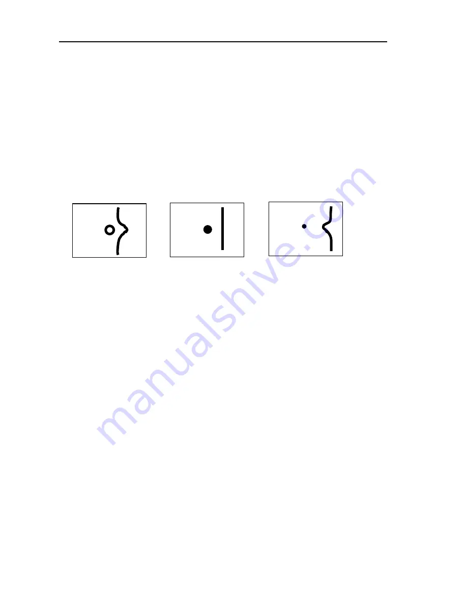
(1) First, set radar range to 0.25nm, FTC to minimum, and GAIN to optimum. Then adjust STC until
the pulse generated by the radar at the center of the screen is a round dot.
(2) Press the “MENU” key and select Adjust
→
TX Timing Adjust.
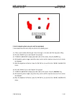
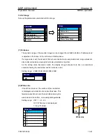
(3) “TX Timing Adjust” will be displayed at the bottom of the screen. Using the rotary control, adjust the
timing until the center dot appears as shown in (b). If there is a linear target such as a bridge or
breakwater, adjust the timing until the target appears straight on the screen.
(4) When the adjustment is finished, press the “ENTER” key to exist from the distance adjustment
screen.
(a)Too far
(b)Correct
(c)Too close
10.4.6.2 Adjusting the angle (Heading Adjust)
This adjustment calibrates the heading direction displayed on the screen to the actual direction of the
ship.
Note: Heading offset value for an open antenna is different from that for a radome antenna.
(1) Find one small target within a 0.5 to 1.5nm range off your bow that is within visible range and is
clearly displayed on the radar screen.
(2) Measure the bearing of this target from the bow using a compass. Call this bearing
θ
c.
(3) Measure the bearing of the target in head up (HU) mode using EBL. Call this bearing
θ
r
.
(4) Calculate the following:
θ
c –
θ
r: if
θ
c is greater than
θ
r
360 –(
θ
r –
θ
c): if
θ
r is greater than
θ
c
Note: This is the azimuth error of your radar at installation. If
θ
c and
θ
r are equal, no
adjustment is needed.
(5) Press the “MENU” key and select Adjust
→
Heading Adjust.
(6) “HEAD DIRECTION ADJUSTMENT” will be displayed at the bottom of the screen. Using the rotary
control, set the value to the azimuth error you have calculated above.
(7) When the adjustment is finished, press the “ENTER” key to exist from the distance adjustment
screen.
10-50
0093161022-06


