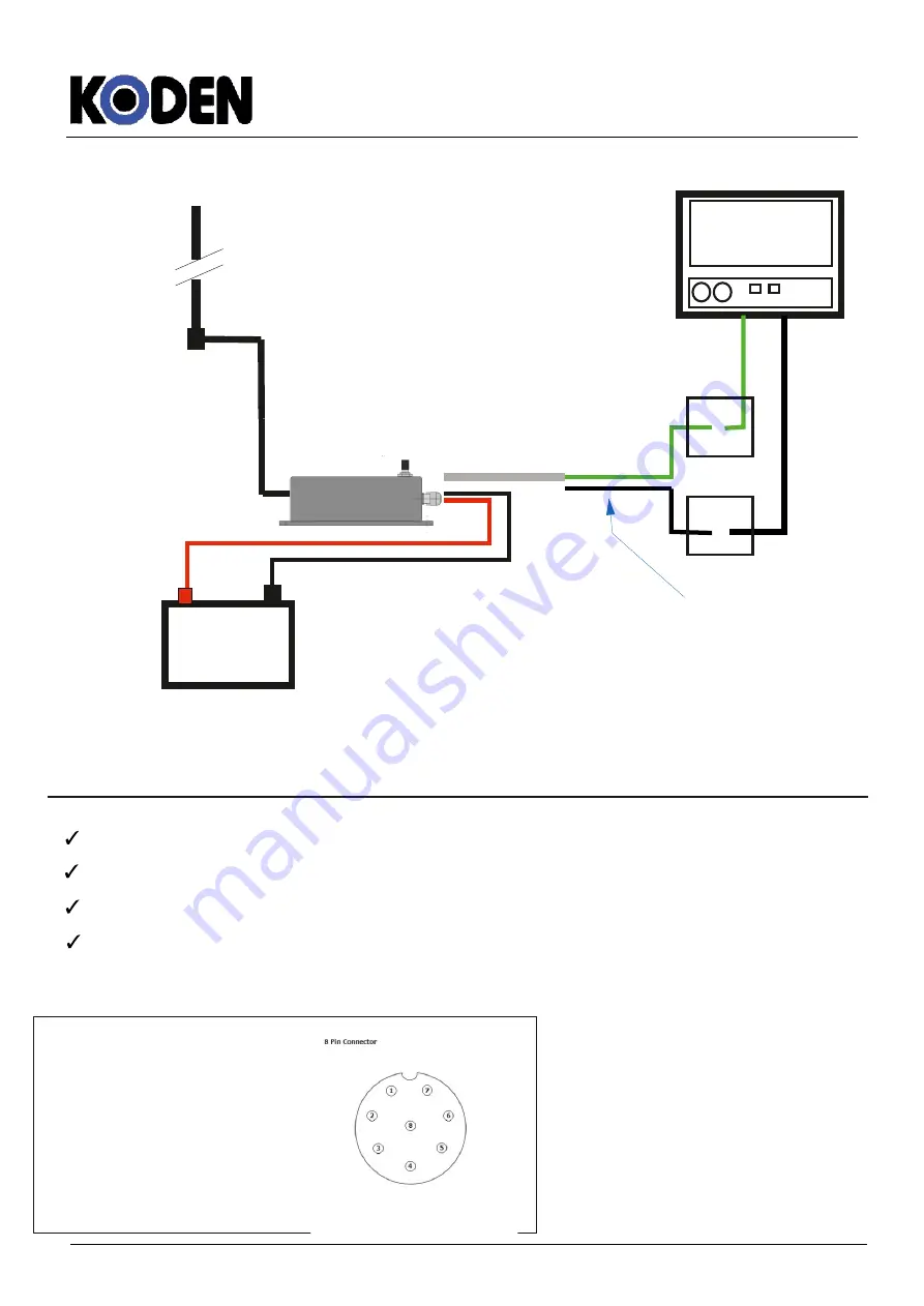
On Board
Antenna 27MHz
24/12 Vdc
Galvanic
isolated
TX -
TX +
Plotter Unit
RX +
RX -
4800 Baud
$RATLL, !AIVDM
5.-Cable distribution by color:
RED
= POWER POSITIVE 9 - 30 Vdc+
BLACK
= GROUND
GREEN
= TX+ DATA OUTPUT 4800 Baud
WHITE
= TX- DATA OUTPUT 4800 Baud
Picture 7
Connection pinout fo the
KGR-100
:
Rg213 Cable
Data
Picture 7
2.- NMEA DATA OUT -
6.- TTL TX (Technical use only)
3.- NMEA DATA OUT +
4.- NC
Data:
1.- Input Voltage 9 - 30 Vdc +
5.- TTL RX (Technical use only)
7.- 5Vdc input TTL (Technical use only)
8.- GND(Common)
Data
This is White Cable
4.- Use of the PKP-27- R00 Receiver
PickPoint-27 USER MANUAL
Page 3 of 6


