background image


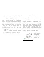
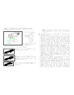
The front and rear feet (2,3) with  transverse screws (6) 

are standard feet with standard prism (4). They are produced 

by the companies manufacturing scopes mounts (for example, 

Ernst Apel Gmbh, Germany)).  

 
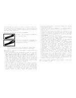
The following types of rails are recommended: 


SP200-64 - for the device NVD-NORS210 

with objective 64mm, 


SP200-100 - for the device NVD-NORS220 

with objective 100mm or NVD-N 

2x Magnification Lens. 


NOTE.  
The rails SP200-64, SP200-100 move the device back. 
This is necessary for some rifles for comfortable 
use.


Adaptation of the device is performed in consistency with 
the following rules: 
-


Check the elevation of the fastening screws (5), pulling 
the rail (4) to the body of the device (1) above the 
upper surface of the rail. The height of elevation must 
not exceed 3.0mm and must not be less than 2.5mm. It is 
especially important when the body of the device has a 
blind aperture with a thread (front hole for the device 
with a 64mm objective). The elevation should not exceed 
3.5mm for through holes and should not be less than 
2.5mm. This requirement can be met by cutting axle length 
of the screws from the side of the thread; 

-


Screw off screws (6) from feets (2,3); 

-


Fix the feets (2,3) to the rail (4). Fasten the feets 
(2,3) to the rifle. Moving the rail in the feets find 
such a position of the device when your eye reaches the 
edge of the Eyepiece Guard or in case of a large caliber 
(for example, .375 H&H Mag) your eye should be situated 
at the distance of 2-5cm from the edge of the rubber 
eyepiece Guard. The device should be located in the 

position which allows comfortable observation without 
stretching forward; 

-


Screw the screws (6) in supports (2,3) from the opposite 
side to fix the selected position of supports (2,3) at 
the rail (4);  

-


Drill the rail(4)at the place of disposition of 
screws(6) using supports (2,3)as conductor. Control the 
depth of drilling not to damage screws (it is desirable 
to use a special accommodation of the firm Ernst Apel 
(Ref.22000)); 

-


Cut an excessive part of the rail (4); 

-


Screw off screws(6) and twirl them in regular position 
into perforated holes through supports (2,3). Fasten 
screws (6) with the fixed composition; 

-


Remove fat from the surface (A)of the rail and from the 
body of device at the place that will be glued; 

-


Prepare the glue (glue is needed, for example, epoxy 
with the tear strength not less than 200kg/cm

2

according to its preparation instruction, and put it on 
the surface (A) of the rail. The surface of the screws 
should not have any glue. This condition is of a 
considerable importance, since it provides an 
opportunity to repair the device and remove the 
alignment rail for further adaptation to another rifle; 

-


Apply a hermetic substance (of silicone type) on the 
thread of the screws (5). It is necessary to exclude the 
hit of moist air into the device and to avoid sweat of 
it; 

-


Fix the rail (4) to the body of the scope with the help 
of the screws (5) cut at the required length; 

-


Remove glue surpluses appeared in the place of alignment 
of the plate with the body with a dry napkin and let the 
glue solidify in accordance with its instruction (for 
example, 24 hours in case of epoxy glue). 

 
Adaptation has been completed and the device is ready for 
use as a hunter’s scope. 


Summary of Contents for NVD-NORS210

Page 1: ...er inc 375H H 416Rigby Lighted high power optics Image protection from lateral and dot light sources Long eye relief Maintains rifle s zero at adjustment of focus Built in high power 75mW hazard free IR illuminator with adjustable power Precision internal windage elevation adjustment Camera and camcorder adaptable Various mount Water resistance Low power consumption Compact Light weight ...

Page 2: ...ion to a hunter s rifle 5 Dimensions of the reticle 8 Adjustment of the scope on the rifle 8 Taking photos and video shooting 8 Maintenance and storage rules 9 Troubleshooting 9 Warranty 10 Acceptance certificate 10 Appearance of the Devices With objective 64mmF 1 2 With Objective 100mm 1 1 5 NVD NORS210 NVD NORS220 6 5 7 3 4 6 5 7 3 4 2 11 1 2 11 1 NVD NORS210 NVD NORS220 12 8 9 10 8 9 10 1 Body ...

Page 3: ...on range decreases in the conditions of weak lighting low transparency of the atmosphere if the target is situated on the dark background plough land stems of trees etc Specifications General NVD NORS210 NVD NORS220 Magnification x 1 6 3 2 2 5 Field of view degree 17 9 11 Objective Focal length mm 64 128 100 F number 1 1 2 1 1 5 Focus range 10m to infinity Eyepiece Focal length mm 16 Eye Relief Di...

Page 4: ...cessories not included in a standard set 2x Magnification Lens for NVD NORS210 only Installation of Batteries Your NVD NORS210 220 works from two AA batteries Be sure that the batteries are in good condition and they are installed in accordance with the picture on the battery compartment To replace the batteries it is necessary to turn off the unit remove the cover of the battery compartment and r...

Page 5: ... USE Adaptation to a Hunter s Rifle Your night vision scope NVD NORS210 220 can be used as a hunter s night vision scope RECOMMENDATION We recommend you verify the order of usage of the hunter s scope on your rifle with the local competent authorities Your night vision scope NVD NORS210 220 can be used with different types of mountings providing reliable fixation of the device on the particular ri...

Page 6: ...The device should be located in the position which allows comfortable observation without stretching forward Screw the screws 6 in supports 2 3 from the opposite side to fix the selected position of supports 2 3 at the rail 4 Drill the rail 4 at the place of disposition of screws 6 using supports 2 3 as conductor Control the depth of drilling not to damage screws it is desirable to use a special a...

Page 7: ...ve The elevation should not exceed 3 5mm for through holes and should not be less than 2 5mm This requirement can be met by cutting axle length of the screws from the side of the thread Remove fat from the surface A of the rail and from the body of device at the place that will be glued Prepare the glue glue is needed for example epoxy with the tear strength not less than 200kg cm2 according to it...

Page 8: ...ing way Fix the scope on the fit of the rifle Set a panel with a target or select the point of aiming Set the rifle on the scoped machine Direct the rifle to the point of aiming by mechanical sight bead with a slot if it is possible At this stage it is suitable to apply laser of cold test shooting LCTS inserted in the barrel of the rifle which indicates geometrical point of the barrel position Uns...

Page 9: ...tion Taking photos with a completely opened diaphragm of the objective is justified for the shooting of quickly moving objects only The TTL system which is installed at most mirror prism cameras easily estimate exposure during the shooting with the device If your camera is not equipped with the TTL system the table can approximately estimate the shutter speed at the diaphragm number of the camera ...

Page 10: ...mage may contain some bright points caused by gradual relief of static electricity from the cathode This feature may appear immediately after the assembly of the device and removal setting of the objective from to the device and it always disappears in 5 14 days of the device utilization storage Koflar I S Toften 40 9280 Storvorde Denmark Phone 45 9831 0496 45 2976 0499 Fax 45 9831 0497 Email info...

Reviews: