background image

INSTALLATION  INSTRUCTIONS  (optional)

Installation in a sliding sash 

window

1. Cut the foam seal(adhesive type) to the proper 
    length and attach it to the window frame,Fig.14.

2. Attach the window slider kit to the window stool. 
   Adjust the length of the window slider kit according 
   to the width of  window, shorten the adjustable window 
   kit if the width of window is less than 27 inches. 
   Open the window sash and place the window slider 
   kit on the window stool.  See Fig.15.

3. Cut the foam seal(adhesive type) to the proper 
    length and attach it on the top of the window. 
   Shown as in Fig.16.

4. Close the sliding sash securely against the window.

5. Cut the foam seal to an appropriate length and 
    seal the open gap between the top window sash 
    and outer window sash. Shown as in Fig.17.

Foam seal

Foam seal A
(adhesive type)

Window
panel

26.5 ~ 48

Fig.14

Fig.15

Fig.16

Fig.17

Window
panel

or

or

26.5 ~ 48

           COOL,HEAT(heat pump type) or  AUTO  
           mode

            FAN,DEHUMIDIIFY or HEAT(electrical heat type)  
            mode 

     Install

     Remove

11

12

INSTALLATION  INSTRUCTIONS

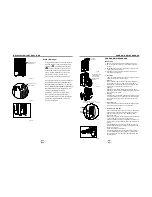
Exhaust hose installation:

     The exhaust hose and adaptor must be installed or removed
     in accordance with the usage mode. 

          For the first time to use the machine,  take the exhaust hose 
          out as shown in Fig.18.          
     1.  Install the adaptor B and adaptor I onto the exhaust hose as 
          shown in Fig.19a or Fig.19b. Refer to the previous pages for 
          window kit installation.
     2.  Place the Exhaust hose over against the air outlet opening
          hook and flat the other end(See Fig.20) for quick installation.


IMPORTANT:

     DO NOT OVER BEND THE EXHAUST HOSE (SEE Fig.22)

Fig.18

Fig.19a

Fig.20

Fig.22


The exhaust hose can be installed into the wall


(Not applicable to the units without adaptor A, expansion

      plugs and wooden screws of Accessories )

.

     1. Prepare a hole in the wall. Install the wall Exhaust adaptor A 
         onto the wall(outside) by using 4 expansion plugs and 
         wooden screws, be sure to fix thoroughly. (See Fig.21)
     2. Attach the Exhaust hose installed adaptor B (round mouth) to 
         wall Exhaust adaptor A.
      

Fig.21

max 120CM

min  30CM

Adaptor A

Expansion plug 
position

Adaptor 
cap


Note: 


Cover the hole using the adaptor cap when not in use. 

Push in

Exhaust hose

Hook

Fig.19b


Note: 

     Extend the both ends of the exhaust hose to a  length of 
     30~50mm before install the adaptor B and apaptor I onto 
     the exhaust hose.

Flat mouth

Use the screws to
install the flat mouth

Flat mouth

Adaptor 1

The exhaust hose  can be compressed or extended 
 moderately according to the installation requirement, 
 but it is desirable to keep the hose length to a minimum.  

Summary of Contents for KAACH12PORA

Page 1: ...WKZ USER MANUAL...

Page 2: ...rs your health when hazardous substances leak into the ground water and find their way into the food chain When using this air conditioner in the European countries the following informa tion must be...

Page 3: ...rules Suggested tools for window kit installation 1 Screwdriver medium size Phillips 2 Tape measure or ruler 3 Knife or scissors 4 Saw In the event that the window kit needs to be cut down in size bec...

Page 4: ...ts in a range of 17 C 62 F to 30 C 88 F or the TIMER setting in a range of 0 24hrs 6 UP and DOWN button NOTE The control is capable of displaying temperature in degrees Fahrenheit or degrees Celsius T...

Page 5: ...Start Stop timed program When the malfunction E1 E2or E4 occurs the Auto Start Stop timed program will also be cancelled SLEEP operation The air conditioner will control room temperature automatically...

Page 6: ...air inlet or outlet of the unit Allow at least 30cm of space from the wall for efficient air conditioning Your window slider kit has been designed to fit most standard Vertical and horizontal window a...

Page 7: ...me to use the machine take the exhaust hose out as shown in Fig 18 1 Install the adaptor B and adaptor I onto the exhaust hose as shown in Fig 19a or Fig 19b Refer to the previous pages for window kit...

Page 8: ...upper filter tab Fig 26 pull the filter out then up Remove the lower filter by loosening the screws taking down the air inlet grille then removing the air filter as shown in Fig 27 28 Cleaning Wash t...

Page 9: ...ature Cooling mode The windows or doors in the room are not closed There are heat sources inside the room Exhaust air duct is not connected or blocked Temperature setting is too high Air filter is blo...

Page 10: ...AIR CONDITIONER REMOTE CONTROL...

Page 11: ...e indoor unit is exposed to direct sunlight the air conditioner may not function properly Use curtains to prevent the sunlight from falling on the receiver If other electrical appliances react to the...

Page 12: ...g 3 MODE Button 3 4 TEMP AUTO COOL DRY HEAT FAN HIGH MED LOW MODE FAN SPEED SWING TIMER ON ECONOMY ON OFF TIMER OFF RESET LOCK 1 2 4 3 6 5 7 8 9 10 11 SET TEMPERATURE C LED DISPLAY 4 SWING Button on s...

Page 13: ...d If FAN mode is selected there will be no display This indicator will be displayed when the unit is operating Displays the selected fan speed AUTO HIGH and LOW Nothing displays when the fan speed is...

Page 14: ...start the air conditioner 3 1 2 1 In the Auto mode the air conditioner can logically choose the mode of Cooling Fan Heating and Dehumidifying by sensing the difference between the actual ambient room...

Page 15: ...s in 30 minutes increments up to 10 hours then at 1 hour increments up to 24 hours 3 After setting the TIMER OFF there will be a one half second delay before the remote controller transmits the signal...

Page 16: ...Example TIMER ON TIMER OFF Off Start Stop operation This feature is useful when you want to start the air conditioner before you wake up and stop it after you leave the house To start the air conditio...

Reviews: