background image

8

3. Specification

3.1 Accessories 

No.

DESCRIPTION

Q’TY

1

Electrical stimulator

1 pc

2

Electrode wires

2 pcs

3

Self-adhesive Electrodes(50mm × 50mm)

4 pcs

4

                                                        Quick Start Guide                                                           1 pc

User manual

1 pc

3.2 Technical information

Channel

Two independent output channels

Power supply

DC6.0V, 1.5×4(AAA) batteries

Waveform

Bi-phase square-wave pulse

Output Voltage

Max:60V(1000 Ω Load)

Output Current

Max:60mA(1000 Ω Load)

Pulse intensity

0-60mA(1000 Ω Load), adjustable

Output intensity

0-60 levels, adjustable

Classification

5°C to 40°C (41 °F to 104 °F ) with a relative humidity of 30%-75%, 
atmospheric pressure from 700 to 1060 Hpa

Storage and Transport conditions

-10°C to 50°C (14 °F to 122 °F ) with a relative humidity of 10%-
90%, atmospheric pressure from 700 to 1060 Hpa 

Dormancy current

Less than 80 (uA)

Working current

Less than 170 (mA)

Dimensions

129.7×76×35.1mm

Weight

Weight 

160g 

(

w

ith batter

ies

)

Tolerance

Tolerance There may be a ±5% tolerance of all setting

s


.

Electrode Detection Function

The amplitude level will be reset to 0 mA when the 

amplitude level is 10 mA or greater and an open circuit 

at either channel is detected.

Summary of Contents for KHTENSPEMSA

Page 1: ......

Page 2: ...rationinthe StandbyOutput mode 16 6 4 Operation in the output mode 17 6 5Operationinthe Setting mode 18 6 6 Operation in the Parameter Setting mode 18 6 7 Memorychecking interface 19 6 8 In all operation interfaces 19 7 Operatinginstruction Formodel FDES102 20 7 1 Turn on 20 7 2 Operationinthe Poweroff mode 20 7 3 Operationinthe StandbyOutput mode 20 7 4 Operationinthe output mode 21 7 5 Operation...

Page 3: ...ission of stimulation in nerve conductions as well as Neuron and muscle tissue in the field of application Electrical stimulation does not replace regular exercising of the muscle but is able to reasonably supplement the effect thereof TENS Transcutaneous Electrical Nerve Stimulation means electrical stimulation of nerves through the skin It is a non medical method of treating pain from certain ca...

Page 4: ...n eruptions e g phlebitis thrombophlebitis varicose veins etc Electrode placements must be avoided that apply current to the carotid sinus region anterior neck or transcerebrally through the head Do not use this device if the patient has a demand type cardiac pacemaker or any implanted defibrillator This device should not be used over poorly enervated areas Use with extreme caution when patient ha...

Page 5: ...r Never use near the heat Stimulation electrodes should never be placed anywhere on the front of the thorax marked by ribs and breastbone but above all not on the two large pectoral muscles Here it can increase the risk of ventricular fibrillation and lead to cardiac arrest Never use on the eye area Never use near the genitals Never use on the areas of the skin which lack normal sensation Apply th...

Page 6: ...ilst driving a car or whilst operating and controlling machinery Never use the device in rooms where aerosols sprays are used or pure oxygen is being administered Do not use it near any highly flammable substances gases or explosives Do not use this device at the same time as other equipment which sends electrical pulses to your body Do not confuse the electrode cables and contacts with your headp...

Page 7: ... selection program selection and pause treatment 5 A increase the output intensity of channel A and the setting parameter 6 A decrease the output intensity of channel A and the setting parameter and unlock button 7 E is Enter confirm button and Treatment location selection button 8 B increase the output intensity of channel B and the setting parameter 9 B decrease the output intensity of channel B...

Page 8: ...sity 7 Electric current symbol 8 Low battery indicator 9 Electrodes connection status indication 10 Massage symbol 11 SPORTS EMS symbol 12 Button locking status symbol 13 TENS symbol 14 Treatment time 15 Timer symbol 16 Time symbol 17 Setting symbol 18 Treatment location indication Where the indicator blinks means the program in use is suitable for those locations 19 Pause symbol 20 Buzzer status ...

Page 9: ...n can be continue the treatment 2 3 3 E BUTTON In stand by mode pressing the E button will go into pre work mode In this state when SPORT or MASSAGE mode are selected pressing the E button can be switch the treatment to suit different body parts In parameter setting mode pressing the E button will switch the different setting parameters 2 3 4 A and B BUTTON In pre work mode pressing the A or B but...

Page 10: ... intensity 0 60 levels adjustable Classification 5 C to 40 C 41 F to 104 F with a relative humidity of 30 75 atmospheric pressure from 700 to 1060 Hpa Storage and Transport conditions 10 C to 50 C 14 F to 122 F with a relative humidity of 10 90 atmospheric pressure from 700 to 1060 Hpa Dormancy current Less than 80 uA Working current Less than 170 mA Dimensions 129 7 76 35 1mm Weight Weight 160g w...

Page 11: ...run in cycles In this program pulse rate 1 to 150Hz pulse width 50 to Pulse Rate Modulation The pulse rate is automatically varied in a cycle time The pulse rate is decreased from its original setting to 60 in setting cycle time 5s keep1second and then increased from 60 to its original setting in nest setting cycle time 5s and keep 1second thus run in cycles In this program pulse rate 1 to 150Hz p...

Page 12: ......

Page 13: ......

Page 14: ......

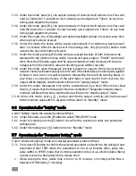
Page 15: ... There are 3 types of therapeutic mode in this stimulator TENS transcutaneous electrical nerve stimulation SPORT and MASSAGE which cold be selected by P button This symbol indicates TENS mode has been selected TENS is blinking This symbol indicates SPORT mode has been selected SPORT is blinking This symbol indicates MASSAGE mode has been selected MASSAGE is blinking This symbol represents EMS wave...

Page 16: ...llow the pre set value This represents lead wire and electrodepadhavebadconnection at channel A This represents output intensity is reducing This represents lead wire and electrode pad have good connection at channel B This represents output intensity is zero This represents lead wire and electrodepadhavebadconnection at channel B This represents unit is locked 5 5 1 Under this mode press A the ou...

Page 17: ... or lead wire is not well connected Meanwhile there will be warning beeps In case there s a connection failure of the electrodes or lead wire for both channels the output will be stopped and stimulator will return to standby output mode 5 5 9 Under this mode therapeutic time will be counted down by a timer When timer shows 0 zero it means that the therapeutic time has completed Therapeutic intensi...

Page 18: ... press A or B button to reduce parameter hold button 2 seconds come into quick adjustment 5 7 4 Under this mode press P button to select setting program 5 7 5 Under this mode there s no key tone during quick adjustment process 5 7 6 When the parameter has been adjusted to the extreme value there will be 3 beep sounds as hints 5 7 7 Under this mode press button return to Parameter setting mode 5 8 ...

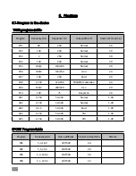
Page 19: ... 100 2 150 250 Han 30 P07 100 250 Burst 30 P08 1 150 120 200 FM PM modulation 30 P09 150 2 200 200 Han 30 P10 100 75 Deeptens 30 U01 1 150 50 300 Normal 1 90 U02 1 150 50 300 Normal 1 90 U03 0 5 5 50 300 Burst 1 90 U04 1 150 50 300 FM 1 90 U05 1 150 50 300 PM 1 90 SPORT Program table Program Frequency Hz Pulse width uS Treatment time Min Remark P01 5 3 18 3 200 300 60 P02 5 5 70 3 200 300 30 P03 5...

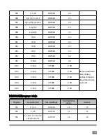
Page 20: ...14 3 40 200 300 30 P15 3 100 200 300 30 U01 1 150 50 300 1 90 Ramp up and down time 1 10sec Contract time and Relax time 0 30 sec can be set U02 1 150 50 300 1 90 U03 1 150 50 300 1 90 U04 1 150 50 300 1 90 U05 1 150 50 300 1 90 MASSAGE Program table Program Frequency Hz Pulse width uS Treatment time Min Remark P01 9 7 5 3 200 300 20 20 P02 2 4 6 200 300 25 25 P03 1 4 20 4 1 4 30 4 1 8 40 4 1 8 50...

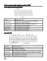
Page 21: ...able Output Current 0 to 35Vpp 500 Ω Load adjustable Output Voltage 0 to 60mA 1000 Ω Load adjustable Cycle time 0 to 60V 1000 Ω Load adjustable 2 Han P06 P09 Waveform Biphasic square wave P R Frequency P06 100 2Hz P09 150 2Hz P W Pulse width P06 150 250us P09 200 200us Output order P06 100Hz 150us first output 3 sec and then output 3 sec 2Hz 250us P09 150Hz 200us first output 3 sec and then output...

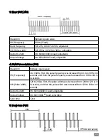
Page 22: ...08 Waveform Biphasic square wave P R Frequency 1 to 150Hz First the pulse frequency was increased from 1 to 150 Hz in 6 seconds and then the pulse frequency was decreased from 150 to 1Hz in 6 seconds P W Pulse width 120 to 200us First the pulse width was decreased from 200 to 120 us in 6 seconds and then the pulse width was increased from 120 to 200us in 6 seconds Output Current 0 to 60mA 1000 Ω L...

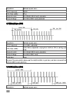
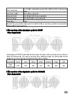
Page 23: ...sic square wave P R Frequency 1 to 150Hz adjustable P W Pulse width 50 to 300us adjustable varying from 100 to 70 in setting cycle time Output Current 0 to 60mA 1000 Ω Load adjustable Output Voltage 0 to 60V 1000 Ω Load Cycle time 5 sec Remark The pulse width is decreased from 100 to 60 in cycle time and then increased from 60 to 100 in next cycle time 7 FM Modulation U04 Waveform Biphasic square ...

Page 24: ...eased from 60 to 100 in next cycle time 8 The waveform of the stimulation modes for SPORT Wave characteristic Each program of SPORT mode both has four phase of output there are Prepare wave Wave A Wave B and Stop wave The wave A and wave B are alternate output The pulse width of each program was can be selecting the detailed information as follows Body parts Hand Arm Chest Waist Buttock Thigh Calf...

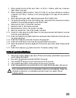
Page 25: ... 3 Wipe the area with the skin preparation your clinician has recommended Let this dry Apply electrodes as directed 4 Many skin problems arise from the pulling stress from adhesive patches that are excessively stretched across the skin during application To prevent this apply electrodes from centre outward avoid stretching over the skin 5 To minimize pulling stress tape extra lengths of lead wires...

Page 26: ...the electrode surface Do not throw away the protective backing because it is reused after the treatment session has been completed 3 Place the tacky surface to the prescribed skin area by pressing the electrode firmly against the skin To remove your electrodes 1 Lift the corner of the electrode and gently remove it from the skin 2 Apply the protective backing to the tacky side of the electrode Pla...

Page 27: ......

Page 28: ...placing lead wire a component may have failed Call the Kogan customer support team Some programs will seem intermittent This is expected Refer to the Program Option Controls in the Operation section for a description of the program option Stimulation invalid Electrodesandtheapplication position is abnormal Unknown Change electrodes and the application position Contact your doctor 9 Storage 1 Remov...

Page 29: ...ent Emissions test Compliance Electromagnetic environment guidance RF emissions CISPR 11 Group 1 The device uses RF energy only for its internal function Therefore its RF emissions are very low and are not likely to cause any interference in nearby electronic equipment RF emissions CISPR11 Class B Harmonic emissions lEC 61000 3 2 Not applicable Voltage fluctuations flicker emissions lEC 61000 3 3 ...

Page 30: ...e Mains power quality should be that of a typical commercial or hospital environment Voltage dips short interruptions and voltage variations on power supply input lines IEC 61000 4 11 5 UT 95 dip in UT for 0 5 cycle 40 UT 60 dip in UT for 5 cycles 70 UT 30 dip in UT for 25 cycles 5 UT 95 dip in UT for 5 sec Not applicable Mains power quality should be that of typical commercial or hospital environ...

Page 31: ...ducted RF lEC 61000 4 6 3 Vrms 150 kHz to 80 MHz Not applicable Radiated RF lEC 61000 4 3 3 V m80 MHz to 2 5 GHz 3 V m 80MHzto800MHz 800MHz to 2 5MHz Where P is the maximum output power rating of the transmitter In watts W according to the Transmitter manufacturer and d Is the recommended separation distance in meters m Field strengths from fixed RF transmitters as determined by an electromagnetic...

Page 32: ...ration distance according to frequency of transmitter m 150 kHz to 80 MHz 80 MHz to 800 MHz 800 MHz to 2 5 GHz 0 01 0 12 0 12 0 23 0 1 0 38 0 38 0 73 1 1 2 1 2 2 3 10 3 8 3 8 7 3 100 12 12 23 For transmitters rated at a maximum output power not listed above the recommended separation distance d in meters m can be estimated using the equation applicable to the frequency of the transmitter where P i...

Page 33: ......

Reviews: