background image

30 


Install App


Download the “Kogan SmarterHome” app from the Play Store (Android) or App Store (iOS). 


Play Store (Android) 


App Store (iOS) 


To register: 

1.


If you already have a SmarterHome account, select ‘Log In’. To register a new 
account, select ‘Sign Up’. 

2.


The system will automatically recognise your country. If needed, you can manually 
select your country from the drop-down box. Enter your email address and tap ‘Get 
Verification Code’ to continue. 

3.


A 6-digit code will be sent to the submitted email address. Enter this code before the 
one-minute timer expires. 

4.


Continue to the next page and complete your SmarterHome profile. 


          CONNECT TO SMARTERHOME™ APP 
 

Summary of Contents for SMARTERHOME KASHSAC80TA

Page 1: ...KOGAN SMARTERHOMETM INVERTER SPLIT SYSTEM 8 2KW REVERSE CYCLE AIR CONDITIONER KASHSAC80TA...

Page 2: ...Safety warnings 3 Overview 6 Installation 11 Before first use 28 Connect to SmarterHomeTM app 30 Google Home control 37 Amazon Alexa control 40 Operation 43 Cleaning care 53 Troubleshooting 62 Notes 6...

Page 3: ...be fitted with means for disconnection from the supply mains having a contact separation in all poles that provide full disconnection under over voltage category III conditions and these means must be...

Page 4: ...ed The use of the conditioner without air filter could cause an excessive accumulation of dust or waste on the inner parts of the device with possible subsequent failures The user is responsible for h...

Page 5: ...ce is not intended for use by persons including children with reduced physical sensory or mental capabilities or lack of experience and knowledge unless they have been given supervision or instruction...

Page 6: ...lter Liquid valve High pressure valve Gas valve Low pressure valve Valve protective cover Connection wiring Drainage pipe Wiring cover Air outlet Air inlet Refrigerant connecting pipe Air deflector an...

Page 7: ...code 2 Lights up during timer operation 3 Sleep mode The shape and position of switches and indicators may be different according to the model but their function is the same Note This figure shown ma...

Page 8: ...8 Remote Control Display Symbol Function Battery indicator Auto mode Cooling mode Dry mode Fan only mode Heating mode ECO mode Timer...

Page 9: ...high Mute TURBO function Up down auto swing Left right auto swing SLEEP function Health function I FEEL function Signal indicator Gentle wind Child Lock Display ON OFF Anti mildew The display and some...

Page 10: ...top or start horizontal louver movement or set the desired left right air flow direction I FEEL To switch the I FEEL function ON OFF MUTE To switch the MUTE function ON OFF Long press to activate deac...

Page 11: ...It is necessary to operate the machine under a controlled procedure to ensure that any risk arising from the combustible gas or vapor during the operation is reduced to minimum Requirements for the to...

Page 12: ...rea m 2 Category LFL kg m 3 h0 m Charge amount M kg Minimum room area m 2 1 224 kg 1 83 6kg 2 44 8kg 3 672 kg 4 89 6kg 6 12k g 7 956 kg R32 0 306 0 6 29 51 116 206 321 543 1 10 19 42 74 116 196 1 8 3...

Page 13: ...should be not surrounded by obstacles or close to any heat source or combustible and or explosive environment If the indoor unit suffers refrigerant leak during the installation it is necessary to im...

Page 14: ...ant Inverter Models Capacity Btu h 9K 12K 18K 36K Length of pipe with standard charge 5m 16ft 5m 16ft 5m 16ft 5m 16ft Length of pipe with standard charge Like North American etc 7 5m 24ft 7 5m 24ft 7...

Page 15: ...er N x m Pound force foot Ibf ft Kilogram force meter kgf m 1 4 6 35 18 20 24 4 27 1 2 4 2 7 3 8 9 52 30 35 40 6 47 4 40 6 47 4 1 2 12 45 50 61 0 67 7 6 2 6 9 5 8 15 88 60 65 81 3 88 1 8 2 8 9 Dedicat...

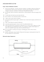
Page 16: ...nting wall strong enough to withstand four times the full weight and vibration of the unit 7 Filter can be easily accessed for cleaning 8 Leave enough free space to allow access for routine maintenanc...

Page 17: ...orizontal state with a spirit level then mark out the screw hole positions on the wall 4 Put down the mounting plate and drill holes in the marked positions using a drill 5 Insert expansion rubber plu...

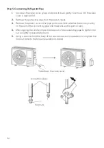
Page 18: ...rotect the connection parts Caution When drilling the wall hole ensure to avoid wires plumbing and other sensitive components Step 4 Connecting Refrigerant Pipe 1 According to the wall hole position s...

Page 19: ...n the port of the connecting pipe and make ensure the port is clean 5 After aligning the centre rotate the nut of the connecting pipe to tighten the nut as tightly as possible by hand 6 Use a torque w...

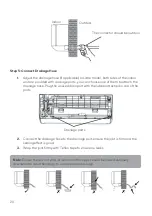
Page 20: ...d drain port with the rubber attached in one of the ports 2 Connect the drainage hose to the drainage port ensure the joint is firm and the sealing effect is good 3 Wrap the joint firmly with Teflon t...

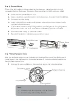
Page 21: ...to the wiring diagram on the electric control box cover And make sure that they are well connected 6 Screw the cable clamp to fasten the cables 7 Reinstall the electric control box cover and front pan...

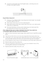
Page 22: ...wall or if you want to be connecting the pipes and wires on the wall do as below 1 Gab both ends of the bottom plate apply a little outward force to take off the bottom plate 2 Hook the top of the in...

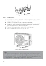
Page 23: ...nstalling the unit where it will be exposed to direct sunlight other wise use a protection if necessary that should not interfere with the air flow 5 Reserve the spaces as shown in the picture for the...

Page 24: ...ons and noise 4 Place the outdoor unit base on the bolts and pre drilled holes 5 Use wrench to fix the outdoor unit firmly with bolts Drainage hose Drainage joint Install 4 rubber stops Optional Note...

Page 25: ...3 According to the wiring diagram pasted inside the wiring cover connect the connecting wires to the corresponding terminals and ensure all connections are firmly and securely 4 Reinstall the cable c...

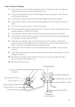
Page 26: ...pipe ports and check whether there is any sundry on the port of the connecting pipe and make ensure the port is clean 4 After aligning the centre rotate the flare nut of the connecting pipe to tighte...

Page 27: ...he pressure for 5 minutes make sure that the rebound of compound gauge pointer does not exceed 0 005 MPa 9 Open the low pressure valve counter clockwise for 1 4 turn with a hexagonal wrench to let a l...

Page 28: ...nit Complete installation of indoor unit air inlet grille and panel Refrigerant leakage detection The piping joint the connector of the two valves of the outdoor unit the valve spool the welding port...

Page 29: ...he drainage hose If the louver and deflectors optional rotate properly 5 Observe the test run state of the air conditioner for at least 30 minutes 6 After a successful test run return the normal setti...

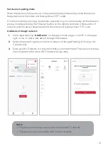
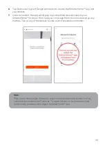
Page 30: ...count select Sign Up 2 The system will automatically recognise your country If needed you can manually select your country from the drop down box Enter your email address and tap Get Verification Code...

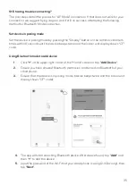
Page 31: ...evice beeps twice and the indoor unit display shows CF code Add device through network 1 Once registered tap Add Device on the app s home page or the in the upper right corner to add a new device thro...

Page 32: ...marterHome device are kept close until connection is complete 6 After successfully being added you will have the option to rename the device and assign it to a location It will now be listed on the ap...

Page 33: ...Using AP Mode to add device 1 Follow the previous steps to select your product type Heating Cooling Air Conditioners 2 Enter your Wi Fi details It is important that your SmarterHome device and the app...

Page 34: ...fter successfully being added you will have the option to rename the device and assign it to a location It will now be listed on the app s home page Tap the device listing to enter its control page No...

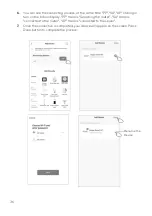
Page 35: ...n 8 seconds until the device beeps twice and the indoor unit display shows CF code Using Bluetooth mode to add device 1 Click in the upper right corner of the Home screen or tap Add Device 2 Ensure yo...

Page 36: ...shining in turn on the indoor display PP means Searching the router SA means connected to the router AP means connected to the server 7 Once the connection is completed your device will appear on the...

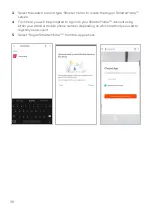
Page 37: ...select the icon top left corner see arrow in the below screenshot to access the Add and manage page 2 Select Set up device then select the Works with Google option GOOGLE HOME CONTROL Note You will n...

Page 38: ...e the Kogan SmarterHome service 4 From here you will be prompted to sign into your SmarterHome account using either your email or mobile phone number depending on which method you used to register you...

Page 39: ...to your SmarterHome account From here you can assign them to rooms and set up any routines Tap on any of the devices to view a list of available commands Note Please note that Google Home can only co...

Page 40: ...elect the icon in the bottom right and select Skills Games from the sidebar 2 Select the search bar and type Smarter Home to locate the Kogan SmarterHome skill AMAZON ALEXA CONTROL Note You will need...

Page 41: ...rHome skill to Alexa 4 From here you will be prompted to sign into your SmarterHome account using either your email or mobile phone number depending on which method you used to register your account 5...

Page 42: ...your SmarterHome account When your devices have successfully connected to the Alexa app you will be able to control your Kogan SmarterHome devices via Alexa s voice commands Note Please note that Alex...

Page 43: ...F T1 climate 15 C 50 C 59 F 122 F Low temperature cooling 15 C 50 C 5 F 122 F T3 climate 15 C 55 C 59 F 131 F With the power supply connected restart the air conditioner after shutdown or switch it to...

Page 44: ...op running The air conditioner will resume heating automatically after defrosting finish Emergency button Open the panel and find the emergency button on the electronic control box when the remote con...

Page 45: ...e Use 2 AAA 1 5V batteries Do not use rechargeable batteries Replace the old batteries with new ones of the same type when the display is no longer legible Do not dispose batteries as unsorted municip...

Page 46: ...r in the indoor unit 3 Never leave the remote control exposed direct sunlight 4 Keep the remote control at a distance of at least 1m from the television or other electrical appliances COOLING MODE The...

Page 47: ...heating function HEAT press the button until the symbol appears on the display With the button or set a temperature higher than that of the room In HEATING operation the appliance can automatically ac...

Page 48: ...etween 0 and 10 hours and by one between 10 and 24 hours 3 Press button a second time to confirm 4 After Timer on setting set the needed mode Cool Heat Auto Fan Dry by press the button And set the nee...

Page 49: ...laps manually the delicate mechanism may be seriously damaged Never put fingers sticks or other objects into the air inlet or outlet vents Such accidental contact with live parts might cause unforesee...

Page 50: ...the remote control to measure the temperature at its current location and send this signal to the air conditioner to optimize the temperature It will automatically deactivate after 2 hours ECO functi...

Page 51: ...AC will appear on the remote controller display and the indoor LED display 1 This function helps carry away the accumulated dirt bacteria etc from the indoor evaporator 2 This function will run for a...

Page 52: ...ive this function will appear on the display Do it again to deactivate it 2 This function will auto close the vertical flaps and give you the comfortable gentle wind feeling Health function Optional 1...

Page 53: ...n to work on a refrigerant circuit should hold a valid and up to date certificate from an assessment authority accredited by the industry and recognizing their competence to handle refrigerants in acc...

Page 54: ...rking adequately sealed or intrinsically safe 5 Presence of fire extinguisher If any hot work is to be conducted on the refrigeration equipment or any associated parts appropriate fire extinguishing e...

Page 55: ...e unlikely to be exposed to any substance which may corrode refrigerant containing components unless the components are constructed of materials which are inherently resistant to being corroded or are...

Page 56: ...air to intrinsically safe components Do not apply any permanent inductive or capacitance loads to the circuit without ensuring that this will not exceed the permissible voltage and current permitted f...

Page 57: ...FN shall then be purged through the system both before and during the brazing process 14 Removal and evacuation When breaking into the refrigerant circuit to make repairs or for any other purpose conv...

Page 58: ...cuum is not possible make a manifold so that refrigerant can be removed from various parts of the system Make sure that the cylinder is situated on the scales before recovery takes place Start the rec...

Page 59: ...of a refrigerant release Consult manufacturer if in doubt The recovered refrigerant shall be returned to the refrigerant supplier in the correct recover cylinder and the relevant waste transfer note a...

Page 60: ...e filter is separated from the unit The filter can be removed by lifting the filter upwards When installing the filter first insert the lower end of the filter screen into the corresponding position o...

Page 61: ...clean and wrung wet rag Clean the removed parts with soapy water and air dry it After cleaning restore the removed parts in turn Service and maintenance When the air conditioner is not in use for a l...

Page 62: ...rty air filter Noise of running water Back flow of liquid in the refrigerant circulation A fine mist comes from the air outlet This occurs when the air in the room becomes very cold for example in the...

Page 63: ...water or objects inside the appliance Very strong smells coming from the appliance ERROR CODE ON THE DISPLAY In case of error the display on the indoor unit shown the following error codes Display De...

Page 64: ...S DNS Security support WEP WPA WPAWAE5128 Network type support STA AP STA AP Max RF Power 18 5 dbm Bluetooth frequency 2 402 2 480GHz Blue tooth RF Power 9 dbm Disposal This marking indicates that thi...

Page 65: ...65 NOTES...

Page 66: ...66...

Page 67: ...67...

Page 68: ...tion We hope that this user guide has given you the assistance needed for a simple set up For the most up to date guide for your product as well as any additional assistance you may require head onlin...

Reviews: