34
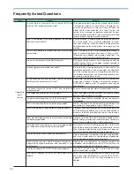
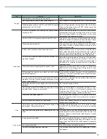
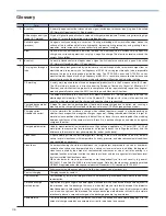
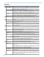
No. Category
①
Category
②
Symptom of problem
Probable cause
Solution
1
2
3
4
5
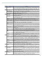
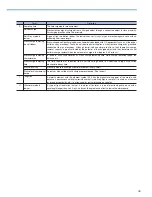
6
7
8
9
10
11
12
13
14
Ionizer
Electrostatic
potential
sensor
Cleanliness
monitor
Common
Blow type
Fan type
EP sensor
CC monitor
(main unit)
LED fails to light even
after power is switched
on. Or it lights
momentarily and then
goes out again.
Red LED (alarm)
lights up.
Ion balance collapses.
Red LED (alarm)
lights up.
No air is being delivered.
LED fails to light even after
power is switched on. Or it
lights momentarily and then
goes out again.
Measurement of GND
does not approach 0V.
LED (red) is lit up.
EP monitor and support
software display values
differ from the actual
charge amounts.
LED (red) fails to blink
even when threshold
value is exceeded.
LED (red) blinking cannot
be reset.
Nothing happens even
after setting the EP
sensor (SET2).
“PEr” display appears on
the monitor.
Power does not switch on.
Power is switched on and
display appears, but then
the LEDs also light up
one by one.
①
No power being
supplied.
①
Discharging needle
dirty or damaged.
②
Discharging needle not
firmly attached.
①
Discharging needle
dirty.
②
Ground not connected.
①
Loose metal cap.
②
Nozzle in contact with
the grounding body.
①
Ionizer throttle valve
too tightly squeezed, or
a piping error.
①
Power switch OFF.
②
Safety circuit activated.
①
Ground not connected.
②
Ground being affected by
nearby charged objects.
①
EP sensor abnormality.
①
EP sensor or EP monitor
measurement distance
settings different from the
actual measurement
distance.
①
Voltage comparison
output valid/invalid
setting invalid.
①
Electric potential in
excess of the set
threshold value detected.
②
Reset cannot be performed
from EP monitor and
support software.
①
“SEnd” not sent after
setting input value.
①
EP sensor abnormality.
② Wiring error.
①
Power cable
disconnected. No
power being supplied.
① Measurement
preparation time.
・
Check that the DC power switch is turned ON. If using an AC adaptor,
check that it is firmly plugged into the electrical outlet.
・
Check that the voltage applied is within product specifications range.
・
Check whether the power and signal cables have breaks.
・
Check that the power and signal cable wiring is correct.
・
Check the tips of all of the discharging needles, and clean the dirty
tips, or replace the damaged ones.
・
Check that the discharging needle (discharging needle unit) is firmly
attached.
・
Check whether the discharging needle is dirty.
・
Check that the ground wire is firmly connected to the ground terminal
on the main body.
・
Check that the ground wire is firmly connected to the ground.
・
Check whether the metal cap is loose.
・
Check whether the metal cap, nozzle, or pipe is in contact with the
grounding body.
・
Check whether the air is throttled too much.
・
Check whether air is being supplied to the ionizer.
・
Check the pneumatic circuit.
・
Check that the switch is ON.
・
Check that the louver (DTRY-ELF series) and discharging needle unit
(DTRY-ELW series) are both firmly set.
・
Check that the ground wire is firmly connected to the ground terminal
on the main body.
・
Check that the ground wire is firmly connected to the ground.
・
Check whether there are charged objects nearby.
・
Repairs required. Consult with Koganei.
・
Check the measurement distance settings and actual measurement
distance.
The check methods are as follows.
・
In the support software, check that the Enabling voltage setting range
was selected in the checkbox.
・
Check that the EP monitor EP sensor setting (SET2) is set to CPE0.
・
Check that the electric potential is lower than the threshold value, and
then reset.
・
Check that the communication cable is connected.
・
After inputting the setting value, send “SEnd”.
・
Check the EP sensor’s alarm LED. If it is lit, it means an EP sensor
abnormality, and that the EP sensor requires repairs. Consult with
Koganei.
・
Check that the wiring is correct.
・
Check that the AC adaptor is firmly plugged into the electrical outlet.
・
Check that the voltage applied is within product specifications range.
・
Check that the AC adaptor plug is firmly inserted into the power
supply jack.
・
This is a normal operation. Since the sampling time for this product is
5 minutes, the first 5 minutes after switching on the power is required
as preparation time. During the preparation time, the level display bar
lights up in the sequence of red blinking
→
orange blinking
→
green
blinking
→
red lit up
→
orange lit up
→
green lit up, to show that
preparation time is in progress. After 5 minutes have elapsed,
measurement starts.
Troubleshooting

