19
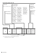
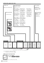
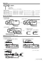
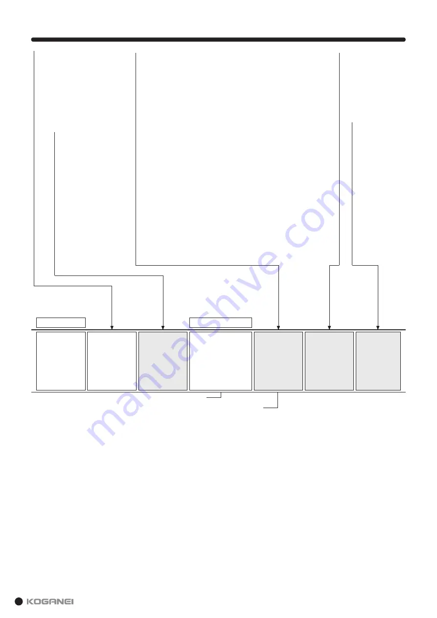
Non-rotating cylinder order code
Operation type
DAL
: Non-rotating double acting type
Cylinder specifications
Blank
: Standard cylinder
Note 1
S
: Cylinder with magnet
YM
DAL
S
×
-ZE135
-ZE155
-ZE175
-ZE235
-ZE255
-ZE275
-ZE101
-ZE102
-ZE201
-ZE202
A
B
G
1
2
·
·
·
n
Basic model
Cylinder bore
×
stroke
Refer to cylinder bore and stroke table in page
R
.
For order code of sensor switch only, refer to page
B
.
Note 1: The standard cylinder does not have built-in magnet for sensor switch.
2: For details of sensor switch, refer to page
A
.
Sensor switch model
Note 2
(for cylinder with magnet)
Lead wire length
Blank
: No sensor switch
-ZE135
: With ZE135
2-wire, solid state
type
With indicator lamp
10 to 28VDC
Horizontal lead wire
-ZE175
: With ZE175
3-wire, solid state
PNP output type
With indicator lamp
4.5 to 28VDC
Horizontal lead wire
-ZE275
: With ZE275
3-wire, solid state
PNP output type
With indicator lamp
4.5 to 28VDC
Vertical lead wire
-ZE155
: With ZE155
3-wire, solid state
NPN output type
With indicator lamp
4.5 to 28VDC
Horizontal lead wire
A
: 1000 mm [39 in.]
B
: 3000 mm [118 in.]
G
: 300 mm [11.8 in.] with
M8 connector,
ZE175
,
ZE275
only
-ZE235
: With ZE235
2-wire, solid state
type
With indicator lamp
10 to 28VDC
Vertical lead wire
-ZE255
: With ZE255
3-wire, solid state
NPN output type
With indicator lamp
4.5 to 28VDC
Vertical lead wire
-ZE101
: With ZE101
2-wire, reed SW type
No indicator lamp
5 to 28VDC
85 to 115VAC
Horizontal lead wire
-ZE102
: With ZE102
2-wire, reed SW type
With indicator lamp
10 to 28VDC
85 to 115VAC
Horizontal lead wire
-ZE201
: With ZE201
2-wire, reed SW type
No indicator lamp
5 to 28VDC
85 to 115VAC
Vertical lead wire
-ZE202
: With ZE202
2-wire, reed SW type
With indicator lamp
10 to 28VDC
85 to 115VAC
Vertical lead wire
Blank
:
No sensor switch
1
: With 1 piece
2
: With 2 pieces
Number of sensor switches
(For sensor cylinder)
Summary of Contents for YMDA Series
Page 34: ...33 MEMO ...


