28
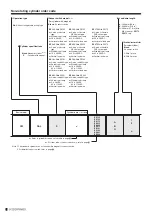
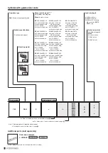
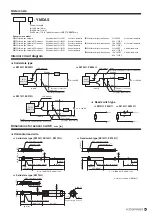
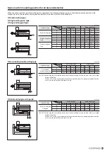
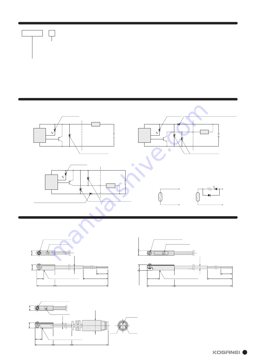
Order code
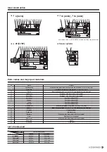
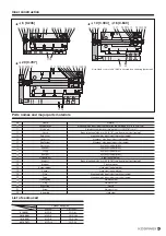
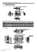
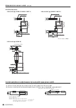
Dimensions for sensor switch
mm [in.]
Horizontal lead wire
60 [2.36]
8 [0.32]
ZE
135
ZE
135
ZE
135
ZE
135
ZE
135
ZE
135
ZE
135
(
R
=
A: 1000 [39], B: 3000 [118])
(6)
([0.236]
)
Maximum sensing location
φ
2.6
[0.102]
M2.5 slotted set screw
Indicator lamp
15.5 [0.610]
R
4.6 [0.181]
4 [0.157]
(
R
=
A: 1000 [39], B: 3000 [118])
Note
: Not available for
ZE101
.
R
60 [2.36]
8 [0.32]
4.6 [0.181]
22.5 [0.886]
(10)
([0.394]
)
Maximum sensing location
φ
2.6
[0.102]
4 [0.157]
M2.5 slotted set screw
Indicator lamp
Note
Solid state type (ZE135
, ZE155
, ZE175
)
Solid state type (ZE175G)
Reed switch type (ZE101
, ZE102
)
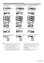
Internal circuit diagram
Reed switch type
Solid state type
Brown
Blue
Brown
(+)
Blue
(−)
ZE135
,
ZE235
ZE175
,
ZE275
ZE155
,
ZE255
ZE101
,
ZE201
ZE102
,
ZE202
Sensor switch model
ZE135
: Solid state type, 2-lead wire
With indicator lamp, 10 to 28V DC
Horizontal lead wire
ZE101
: Reed switch type, no indicator lamp
5 to 28VDC
Horizontal lead wire
ZE155
: Solid state type, 3-lead wire NPN output type
With indicator lamp, 4.5 to 28V DC
Horizontal lead wire
85 to 115VAC
ZE175
: Solid state type, 3-lead wire PNP output type
With indicator lamp, 4.5 to 28V DC
Horizontal lead wire
ZE102
: Reed switch type, with indicator lamp 10 to 28VDC
Horizontal lead wire
ZE235
: Solid state type, 2-lead wire
With indicator lamp, 10 to 28V DC
Vertical lead wire
85 to 115VAC
ZE255
: Solid state type, 3-lead wire NPN output type
With indicator lamp, 4.5 to 28V DC
Vertical lead wire
ZE201
: Reed switch type, no indicator lamp
5 to 28VDC
Vertical lead wire
ZE275
: Solid state type, 3-lead wire PNP output type
With indicator lamp, 4.5 to 28V DC
Vertical lead wire
85 to 115VAC
ZE202
: Reed switch type, with indicator lamp 10 to 28VDC
Vertical lead wire
85 to 115VAC
Lead wire length
A
: 1000 mm [39 in.]
B
: 3000 mm [118 in.]
G
: 300 mm [11.8 in.] with M8 connector,
ZE175
,
ZE275
only
- YMDAS
φ
9
[0.354]
Indicator lamp
ZE
175
M2.5 slotted set screw
15.5
[0.610]
(6)
([0.236]
)
φ
2.6
[0.102]
(300 [11.8]
)
31 [1.22]
4 (OUT
)
1
(+)
3
(−)
Connector pin location
Maximum
sensing position
4.6 [0.181]
4 [0.157]
Load
Switch
main circuit
Blue
Brown
(
−
)
(+)
(Switch)
(External connection)
Zener diode
(for surge suppression)
LED indicator
10 to 28VDC
Load
Switch
main circuit
Blue
Black
(
−
)
(+)
(Switch)
(External connection)
Zener diode
(for surge suppression)
LED indicator
4.5 to 28VDC
Brown
Diode
(for protection against reverse connection)
Load
Switch
main circuit
Blue
Black
3
(−)
1
(+)
4
(Switch)
(External connection)
Zener diode
(for surge suppression)
LED indicator
4.5 to 28VDC
Brown
Diode
(for protection against reverse connection)
Summary of Contents for YMDA Series
Page 34: ...33 MEMO ...


