29
z
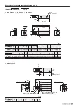
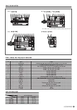
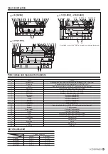
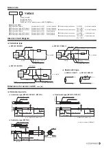
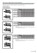
Vertical lead wire
M2.5 slotted set screw
Indicator lamp
Note
Maximum sensing location
φ
2.6 [0.102]
60 [2.36]
8 [0.32]
11.5 [0.453]
22
[0.866]
(ℓ
=
A:
1000 [39],
B:
3000 [118]
)
4.6 [0.181]
4 [0.157]
(10)
([0.394]
)
z
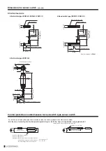
Solid state type (ZE235
, ZE255
, ZE275
)
z
Solid state type (ZE275G)
z
Reed switch type (ZE201
, ZE202
)
8 [0.32]
(ℓ
=
A:
1000 [39],
B:
3000 [118]
)
ZE
235
ZE
235
ZE
235
ZE
235
ZE
235
ZE
235
ZE
235
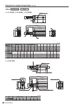
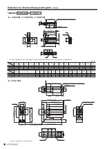
M2.5 slotted set screw
Indicator lamp
10.5 [0.413]
(6)
([0.236]
)
Maximum sensing location
φ
2.6 [0.102]
60 [2.36]
15
[0.591]
4.6 [0.181]
4 [0.157]
Note: Not available for
ZE201
.
ZE
275
4 [0.157]
φ
2.6 [0.102]
φ
9
[0.354]
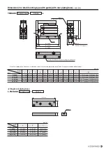
Indicator lamp
Maximum sensitivity location
1
(+)
3
(−)
4 (OUT)
(
300
)
([11.8]
)
10.5
[0.413]
31 [1.22]
Connector pin location
M2.5 slotted set screw
(6)
([0.236]
)
15
[0.591]
4.6 [0.181]
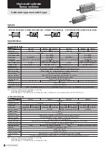
Contact protection countermeasure for reed switch type sensor switch
z
In the case of connecting inductive load (electromagnetic relay, etc.)
z
In the case of capacitive surge generated
(when lead wire length exceeds 10 m [32.8 ft])
For stable use of reed switch type sensor switches, take the contact protection countermeasure below.
Inductive load
Surge absorption element
In the case of DC: Diode or CR, etc.
In the case of AC: CR, etc.
Diode: More than the circuit current for the forward current,
and dielectric strength of more than 10 times
the circuit voltage for the reverse direction.
C: 0.01 to 0.1
μ
F
R: 1 to 4 k
Ω
C surge suppressor
As close as possible
Load
Choke coil: 1 to 5 mH
Sensor switch
Dimensions for sensor switch
mm [in.]
Summary of Contents for YMDA Series
Page 34: ...33 MEMO ...


