30
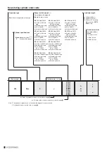
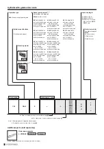
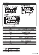
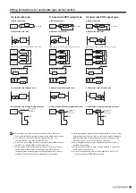
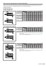
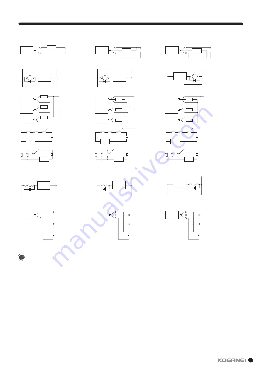
Wiring instructions for solid state type sensor switch
Sensor switch
Brown
Blue
Load
10 to 28VDC
z
Basic connection
z
Connection with relay
z
Connection with relay
CR
Sensor switch
(+)
(−)
Brown
Blue
AND (serial) connection, OR (parallel) connection
CR
Sensor switch
(+)
(−)
Black
Blue
Brown
Sensor switch
Sensor switch
Relay
Sensor switch
Relay
Relay
Sensor switch
Sensor switch
Sensor switch
Relay
Relay
Relay
Load
Relay contact
Relay contact
Load
Load
Relay contact
Relay contact
Load
(+)
(−)
Brown
Blue
Sensor switch
(+)
(−)
Black
Blue
Brown
Sensor switch
Brown
Blue
Programmable
controller
input terminal
(+)
COM.
z
Connection with solenoid valve
z
Connection with programmable controller
z
Connection with programmable controller
z
Connection with solenoid valve
Sensor switch
Brown
Blue
Programmable
controller
input terminal
(+)
COM.
Black
AND (serial) connection, OR (parallel) connection
Sensor switch
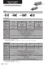
z
2-lead wire type
Sensor switch
Brown
Blue
4.5 to 28VDC
Black
Load
z
Basic connection
z
3-lead wire NPN output type
z
Connection with relay
Sensor switch
(+)
(−)
Black
Brown
Blue
Sensor switch
Sensor switch
Sensor switch
Relay
Relay
Relay
Load
Relay contact
Relay contact
Load
Sensor switch
(+)
(−)
Black
Brown
Blue
z
Connection with programmable controller
z
Connection with solenoid valve
Sensor switch
Brown
Blue
Programmable
controller
input terminal
(
−
)
COM.
Black
AND (serial) connection, OR (parallel) connection
Sensor switch
Brown
Blue
4.5 to 28VDC
Black
Load
z
Basic connection
z
3-lead wire PNP output type
CR
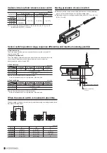
Note
Note
1.
Follow wire color code for proper connection. Since there is no
overcurrent protection, improper wiring will break the sensor switch.
2.
For inductive load such as electromagnetic relay, etc., it is
recommended to use surge protective diode.
3.
Since the circuit voltage drops in proportion to the number of sensor
switches, avoid using AND (serial) connection.
4.
When using OR (parallel) connection, direct connection of sensor
switch outputs (black wires, for example) is possible. But, the
leakage current increases proportionally by the number of sensor
switches. Therefore, be cautious against load return failure.
5.
Avoid use in places where external magnetic field is strong, or near
large current such as power lines, as the sensor switch is magnetic
induction type. And, magnetic material should not be used in the
mounting portion. This may cause erratic operations.
6.
Do not apply excessive force by pulling the lead wire forcibly, or
bending it excessively.
7.
Avoid use in environment where it may be exposed to chemically
active agents or gasses, etc.
8.
For use in atmosphere where it may be exposed to water or oil,
consult your nearest KOGANEI sales office.
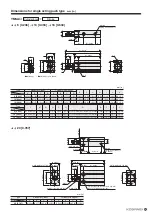
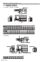
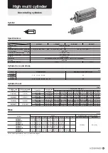
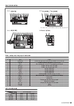
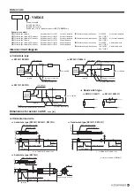
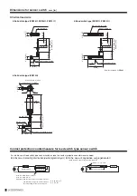
Summary of Contents for YMDA Series
Page 34: ...33 MEMO ...


