background image

4

Always read these precautions carefully before use.

CAUTION


When mounting the product, leave room for adequate working 
space around it. Failure to do so will make it more difficult to 
conduct daily inspections or maintenance, which could eventu-
ally lead to system shutdown or damage to the product.


Do not bring any magnetic media or memory within one meter 
[3.28 ft] of the product. Doing so creates the risk of damage to 
data on the magnetic media due to magnetism.


The sensor switch should not be used in a location where high 
current or magnetic field is generated. This may cause the 
machine to malfunction.
Also avoid using magnetic material for any parts used for 
mounting. Doing so creates the risk of magnetism leakage that 
causes malfunctions.


Do not bring the product close to magnetized body. Bringing 
the product close to magnetized body or the location where 
high magnetic field is generated can magnetize the main body 
or table, resulting the malfunction of sensor switches or defec-
tive operation due to attachment of the iron powder.


Make absolute sure that sensor switches of other companies 
are not used for this product.
Failure to do so can lead to malfunctions or runaway 
operations.


Do not scratch, dent, or deform the actuator by climbing on the 
product, using it as a scaffold, or placing objects on top of it. 
Doing so creates the risk of damage to or breakage of the 
product, resulting in operational shutdown or degraded 
performance.


Always post an "operations in progress" sign for installations, 
adjustments, or other operations, to avoid unintentional 
supplying of air or electrical power, etc. Unintended power or 
air supply can cause electric shock or sudden cylinder 
movement, creating the risk of personal injury.


Do not apply excessive load to the cords, such as the lead 
wires of sensor switches mounted on the cylinder, in such 
manner as pulling, carrying by hands or placing heavy object 
on the cords. Doing so may cause the leak current or defective 
continuity, leading to fire, electric shock or malfunctions.


When the pressure is increased by external force, make sure 
to attach the relief equipment or any other means not to 
exceed the specified operating pressure of the cylinder. 
Pressure exceeding the specified operating pressure may lead 
to malfunction and breakdown.


When the machine has been idle for over 48 hours or is in first 
operation after storage, it is possible that the contacting parts 
may have become stuck, leading to operation delays or 
sudden movements. In initial operation, be sure to perform trial 
operation to check whether the machine works properly.


Never use the product in direct sunshine-suffered location like 
beach, near mercury lamp, or near a product likely to produce 
ozone. Deterioration of rubber parts caused by ozone may 
reduce the performance and function or stop the function.


Because KOGANEI products may be used under a wide 
variety of conditions, decisions concerning conformance with 
a particular system should be made upon the careful 
evaluation by the person in charge of system design. 
Assurances concerning expected system performance and 
safety are the responsibility of the designer who decides 
system conformity. Be sure to use the latest catalogs and 
technical materials to study and evaluate specification details, 
to consider the possibility of machine breakdown, and to 
configure a system that ensures fail-safe safety and reliability.


Do not use in locations that are subject to direct sunlight 
(ultraviolet rays), in locations with dust, salt, or iron particles, 
or in locations with media and/or ambient atmosphere that 
include organic solvents, phosphate ester type hydraulic oil, 
sulfur dioxide, chlorine gas, acids, etc. Such uses could lead to 
early shutdown of some functions, a sudden degradation of 
performance, and a reduced operating life. For details on 
materials used in the product, refer to the description of major 
parts.


Always observe the following items.
KOGANEI shall not be held responsible for any problems that 
occur as a result of these items not being properly observed.

1.

  When using this product in pneumatic systems, always use genu-

ine KOGANEI parts or compatible products (recommended parts).

  When conducting maintenance and repairs, always use genuine 

KOGANEI parts or compatible products (recommended parts).

  Always observe the prescribed methods and procedures.

2.

 Never attempt inappropriate disassembly or assembly of the prod-

uct relating to basic construction, or its performance or functions.

KOGANEI shall not be held responsible for any problems that occur 
as a result of these safety precautions not being properly observed.

Others

ATTENTION


Whenever considering use of this product in situations or 
environments not specifically noted in the "catalog" or "instruction 
manual", or in applications where safety is an important requirement 
such as in aircraft facilities, combustion equipment, leisure equipment, 
safety equipment, and other places where human life or assets may 
be greatly affected, take adequate safety precautions such as allowing 
plenty of margin for ratings and performance, or fail-safe measures.
Be sure to contact KOGANEI before use in such applications.


Always check the "catalog" and other reference materials for 
product wiring and piping.


Moving parts of machine and devices should be isolated with a 
protection cover so as not to be directly contacted by human body.


Do not configure the control that may cause a workpiece to 
drop when in power outage.
Be sure to configure the work/table-drop prevention control for 
the case of power outage or emergency stop of the machine.


When handling the product, wear protective gloves, safety 
glasses, safety shoes, etc., as required.


When the product can no longer be used or is no longer 
necessary, dispose of it appropriately as industrial waste.


Pneumatic equipment can exhibit degraded performance and 
function over its operating life. Always conduct daily inspections of 
the pneumatic equipment, and confirm that all requisite system 
functions are satisfied, to prevent accidents from happening.


For inquiries about the product, consult your nearest KOGANEI 
sales office or KOGANEI overseas group. The addresses and tele-
phone numbers are shown on the back cover of this catalog.

Safety Precautions (High multi cylinder)

Warranty and General Disclaimer

1.

 Warranty Period

The warranty period for KOGANEI products is 180 days from 
the date of delivery.

2.

  Scope of Warranty and General Disclaimer

(1)  The KOGANEI product warranty covers individual products. When a 

product purchased from KOGANEI or from an authorized 
KOGANEI distributor malfunctions during the warranty period in a 
way that is attributable to KOGANEI responsibility, KOGANEI will 
repair or replace the product free of charge. Even if a product is still 
within the warranty period, its durability is determined by its 
operation cycles and other factors. Contact your nearest KOGANEI 
sales office or the KOGANEI overseas group for details.

(2)  KOGANEI shall not be held responsible for any losses or for 

any damage to other machinery caused by breakdown, loss 
of function, or loss of performance of KOGANEI products.

(3)  KOGANEI shall not be held responsible for any losses 

due to use or storage of the product in a way that is 
outside of the product specifications prescribed in 
KOGANEI catalogs and the instruction manual, and/or 
due to actions that violate the mounting, installation, 
adjustment, maintenance and other safety precautions.

(4)  KOGANEI shall not be held responsible for any losses 

caused by breakdown of the product due to factors 
outside the responsibility of KOGANEI, including but not 
limited to fire, natural disaster, the actions of third 
parties, and intentional actions or errors by you.

Summary of Contents for YMDA Series

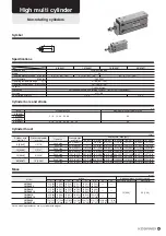
Page 1: ... s s s s s s s s s s s s s s s s s s s s s s s a a a a a a a a a a a a a a a a a a a a ar r r r r r r r r r re e e e e e e R R R R R R R R R R R R R R R R R R R R R R R R R Ro o o o o o o o o o o o o o o o oH H H H H H H H H H H H H H H H H H H H HS S S S S S S S S S S S S C C C C C C C C C C C Co o o o o o o om m m m m m m m m m m m m m m m m m m m m m m m m mp p p p p p p p p p p p p p p p p p p...

Page 2: ...ced in the sensor mounting groves located on the 2 faces of main body Compact direct mounting Standardizing cylinders with guides The embedded sensor switch is employed Body through hole for vertical mounting Body through hole counterbore for flat surface mounting Body mounting tap hole of head side flange type Good for use in tight places embedded type sensor switch Body mounting tap hole of rod ...

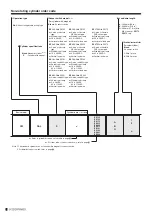
Page 3: ...ting type Single acting push type and Single acting pull type K Order code L Inner construction and parts names M Dimensions O Non rotating cylinders R Order code S Inner construction and parts names T Dimensions U Cylinders with guides V Order code W Inner construction and parts names X Dimensions Y Sensor switches A Order code Internal circuit diagram B Contact protection countermeasure wiring i...

Page 4: ...o basic construction or to its performance or functions Doing so creates the risk of injury electric shock fire etc Do not allow water to splash on the product Water spraying on the product washing the product or using the product under water creates the risk of malfunction leading to injury electric shock fire etc While the product is in operation avoid touching it with your hands or otherwise ap...

Page 5: ...sudden degradation of performance and a reduced operating life For details on materials used in the product refer to the description of major parts Always observe the following items KOGANEI shall not be held responsible for any problems that occur as a result of these items not being properly observed 1 When using this product in pneumatic systems always use genu ine KOGANEI parts or compatible p...

Page 6: ...e current even at off condition to activate the internal circuit Ensure that they satisfy the following inequality Input off current of programmable controller Leakage current If above inequality is not satisfied select 3 lead wire solid state sensor switch And if n pieces sensors are connected in parallel the leakage current increases by n times 1 Do not apply an external magnetic field to the se...

Page 7: ...voltage lines Avoid wiring in parallel to or shared in the same conduit with power line and high voltage line Such wiring could cause the sensor switch and control circuit to suffer erratic operation by electric noise 3 Be cautious against not bending the lead wire repeatedly or applying tension force to the wire Applying repeated bending stress or tension force to the lead wire may cause the wire...

Page 8: ...Page F 2 When an inductive load will be connected to reed sensor switches or if capacitive surge will occur take some contact protection countermeasures For contact protection countermeasures refer to Page C 1 Do not place your hands in the cylinder operating direction 2 In the initial operation be cautious against cylinder operating direction 3 When the cylinder is retracting be cautious against ...

Page 9: ...llowing tightening torque When using female threads of the main body for mounting tighten the screw under the tightening torque shown in Mounting Avoid the following usages 9 When thrust of a cylinder with guide directly apply to the plate apply the force to the rod axis center Cylinder bore mm in 6 0 236 10 0 394 16 0 630 20 0 787 M3 0 5 M4 0 7 M5 0 8 1 08 9 56 0 59 5 22 2 45 21 68 1 37 12 13 5 1...

Page 10: ...t mm in Pitching Mp Yawing My Rolling Mr Guide center location B A Stroke For each moment center position use the guide center location shown in the figure as the reference Applications exceeding the allowable bending moment may damage the guide portion and deteriorate the accuracy thereby affecting the operating life Symbol Center of the guide Lp A St Fp Mp Fr Mr Lr B Center of the guide Ly A St ...

Page 11: ... 05 0 10 0 15 0 20 0 10 20 30 40 50 9 N 7 N 5 N mm mm Stroke 1 mm 0 0394 in 1 N 0 2248 lbf Deflection Cylinder bore φ6 0 236 in Cylinder bore φ16 0 630 in Cylinder bore φ10 0 394 in Cylinder bore φ20 0 787 in W N Stroke 1 Remove a plug on the head cover To attach the plug again tighten at the tightening torque of 0 59 N m 5 22 in lbf 2 Place supplied O rings as shown in the figure and install the ...

Page 12: ...16 90 0 5 73 14 1 3 17 10 6 2 38 9 2 2 07 5 7 1 28 39 3 8 83 29 5 6 63 29 6 6 65 19 8 4 45 100 5 22 59 86 19 33 79 1 17 78 64 6 14 52 157 35 29 117 5 26 41 138 2 31 07 98 7 22 19 0 6 87 16 9 3 80 12 7 2 85 12 0 2 70 7 8 1 75 47 1 10 59 35 3 7 94 37 5 8 43 25 7 5 78 120 6 27 11 103 2 23 20 99 2 22 30 81 8 18 39 188 4 42 35 141 31 70 169 6 38 13 122 2 27 47 0 7 102 19 7 4 43 14 8 3 33 14 8 3 33 9 9 ...

Page 13: ...A16 YMSAS16 YMSA20 YMSAS20 10 28 0 99 31 1 09 37 1 31 43 1 52 78 2 75 88 3 10 157 5 54 185 6 53 15 31 1 09 34 1 20 41 1 45 47 1 66 84 2 96 94 3 32 170 6 00 198 6 98 ZE A ZE G 15 0 53 ZE B 35 1 23 g oz Single acting pull type Note Values in parentheses are for cylinder with magnet 5 25 0 88 28 0 99 35 1 23 41 1 45 75 2 65 85 3 00 142 5 01 170 6 00 Stroke Additional mass for sensor switch Model YMTA...

Page 14: ...236 φ 10 0 394 φ16 0 630 Single acting push type φ 6 0 236 φ 10 0 394 φ16 0 630 φ 20 0 787 φ 20 0 787 Sensor cylinder Note Head cover of φ16 0 630 is secured by a snap ring hard steel Note Head cover of φ16 0 630 is secured by a snap ring hard steel ...

Page 15: ...c rubber NBR Synthetic rubber NBR Synthetic rubber NBR Synthetic rubber NBR Steel nickel plated zinc plated for φ20 0 787 only Brass aluminum alloy for φ20 0 787 only special anti rust treated Plastic magnet Brass aluminum alloy for φ20 0 787 only special anti rust treated Piano wire Porous metal Aluminum alloy special anti abrasion treated Plastic Hard steel List of seals used Parts names and maj...

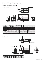
Page 16: ...e φ6 0 236 Depth 5 0 197 both sides φ4 5 0 177 Counterboreφ7 6 0 299 Depth6 5 0 256 bothsides S 24 0 945 25 0 984 33 1 299 T 13 0 512 15 0 591 20 0 787 V 3 0 118 5 0 197 6 0 236 Y 19 0 748 19 0 748 25 0 984 Y S Y G φV P 2 M5 0 8 Piping connection port 2 φO M D Stroke N A Stroke E B Stroke C Stroke F H J 2 L K I T 2 L Q 2 R 12 0 472 17 0 669 33 1 299 42 1 654 20 0 787 26 1 024 12 0 472 5 0 197 15 0...

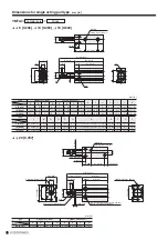
Page 17: ...Type Symbol Symbol A 48 1 890 53 2 087 58 2 283 Standard cylinder B 33 1 299 36 1 417 40 1 575 C 26 1 024 28 1 102 31 1 220 D 7 0 276 7 5 0 295 8 0 315 A 53 2 087 58 2 283 63 2 480 Cylinder with magnet B 38 1 496 41 1 614 45 1 772 C 31 1 220 33 1 299 36 1 417 D 12 0 472 12 5 0 492 13 0 512 E 15 0 591 17 0 669 18 0 709 F 7 0 276 8 0 315 9 0 354 G 11 0 433 11 0 433 14 0 551 H 7 0 276 10 0 394 12 0 4...

Page 18: ...15 9 0 354 R φ3 4 0 134 Counterboreφ6 0 236 Depth5 0 197 bothsides φ3 4 0 134 Counterboreφ6 0 236 Depth5 0 197 bothsides φ4 5 0 177 Counterboreφ7 6 0 299 Depth6 5 0 256 bothsides S 24 0 945 25 0 984 33 1 299 T 13 0 512 15 0 591 20 0 787 V 3 0 118 5 0 197 6 0 236 Y 19 0 748 19 0 748 25 0 984 mm in Y S Y G φV P 2 φO M D Stroke N E Stroke B Stroke C Stroke F H J 2 L K I T 2 L Q M5 0 8 Piping connecti...

Page 19: ...1 167 5 89 195 6 88 15 34 1 20 37 1 31 44 1 55 50 1 76 87 3 07 97 3 42 180 6 35 208 7 34 20 37 1 31 40 1 41 48 1 69 54 1 90 93 3 28 103 3 63 193 6 81 221 7 80 25 40 1 41 43 1 52 52 1 83 58 2 05 99 3 49 109 3 84 206 7 27 234 8 25 30 43 1 52 46 1 62 56 1 98 62 2 19 105 3 70 115 4 06 219 7 72 247 8 71 40 245 8 64 273 9 63 50 271 9 56 299 10 55 Cylinder thrust 0 1 15 7 9 1 78 5 9 1 33 20 1 4 52 17 2 3...

Page 20: ...ire ZE275 With ZE275 3 wire solid state PNP output type With indicator lamp 4 5 to 28VDC Vertical lead wire ZE155 With ZE155 3 wire solid state NPN output type With indicator lamp 4 5 to 28VDC Horizontal lead wire A 1000 mm 39 in B 3000 mm 118 in G 300 mm 11 8 in with M8 connector ZE175 ZE275 only ZE235 With ZE235 2 wire solid state type With indicator lamp 10 to 28VDC Vertical lead wire ZE255 Wit...

Page 21: ...ed Aluminum alloy special anti rust treated Synthetic rubber NBR Synthetic rubber NBR Synthetic rubber NBR Synthetic rubber NBR Steel nickel plated zinc plated for φ20 0 787 only Brass aluminum alloy for φ20 0 787 only special anti rust treated Plastic magnet Stainless steel Aluminum alloy special anti abrasion treated Aluminum alloy anodized Aluminum alloy special anti abrasion treated Plastic Ha...

Page 22: ...071 M3 0 5 10 0 394 53 2 087 31 1 220 23 0 906 2 5 0 098 58 2 283 36 1 417 28 1 102 7 5 0 295 22 0 866 8 0 315 11 0 433 10 0 394 7 0 276 2 4 0 094 M4 0 7 16 0 630 58 2 283 35 1 378 26 1 024 3 0 118 63 2 480 40 1 575 31 1 220 8 0 315 23 0 906 9 0 354 14 0 551 12 0 472 8 0 315 3 2 0 126 M5 0 8 Type L M N O P Q R S T V Y Z AA AB AC AD Symbol Bore 6 0 236 M3 0 5 Depth 5 0 197 15 5 0 610 10 5 0 413 3 4...

Page 23: ...9 26 140 7 31 63 120 4 27 07 219 8 49 41 164 5 36 98 Air pressure Mpa psi 3 0 118 5 0 197 6 0 236 10 0 394 Piston rod diameter mm in 28 2 0 0437 21 2 0 0329 78 5 0 1217 58 9 0 0913 201 0 312 172 0 267 314 0 487 235 0 364 Pressure area mm2 in2 Operation Pitching Rolling Yawing Cylinder portion Guide portion Double acting type Air 1 05 152 0 60 32 140 Rubber bumper Not required if used use turbine o...

Page 24: ...tate PNP output type With indicator lamp 4 5 to 28VDC Horizontal lead wire ZE275 With ZE275 3 wire solid state PNP output type With indicator lamp 4 5 to 28VDC Vertical lead wire ZE155 With ZE155 3 wire solid state NPN output type With indicator lamp 4 5 to 28VDC Horizontal lead wire A 1000 mm 39 in B 3000 mm 118 in G 300 mm 11 8 in with M8 connector ZE175 ZE275 only ZE235 With ZE235 2 wire solid ...

Page 25: ...s steel hard chrome plated for φ20 0 787 only Brass aluminum alloy for φ20 0 787 only special anti rust treated Aluminum alloy special anti abrasion treated Aluminum alloy special anti rust treated Aluminum alloy special anti rust treated Synthetic rubber NBR Synthetic rubber NBR Synthetic rubber NBR Synthetic rubber NBR Steel nickel plated Brass aluminum alloy for φ20 0 787 only special anti rust...

Page 26: ...g thread φ 6 0 236 φ10 0 394 φ16 0 630 Cylinder bore Stroke mm in Symbol Bore A B C D E F G H I J K L M N O 6 0 236 44 1 732 33 1 299 26 1 024 7 0 276 11 0 433 7 0 276 11 0 433 5 0 197 2 5 0 098 8 0 315 M3 0 5 M3 0 5 Depth 5 0 197 15 5 0 610 10 5 0 413 M3 0 5 10 0 394 49 1 929 36 1 417 28 1 102 7 5 0 295 13 0 512 8 0 315 11 0 433 6 0 236 3 0 118 8 0 315 M3 0 5 M3 0 5 Depth 5 0 197 18 0 709 10 5 0 ...

Page 27: ...02 79 3 110 B 15 0 591 15 0 591 21 0 827 26 1 024 C 10 5 0 413 10 5 0 413 11 0 433 11 0 433 mm in G I J H F E M3 0 5 Extended side piping port O ring D K2 K1 C Stroke B Stroke A Stroke M3 0 5 Retracted side piping port Hexagon socket head screw for securing rear piping base C B A Stroke M3 0 5 Symbol Cylinder bore Stroke Cylinder bore Stroke A 51 2 008 56 2 205 63 2 480 81 3 189 B 49 1 929 52 2 04...

Page 28: ... Note 2 Environmental protection Operation indicator Lead wire Ambient temperature Storage temperature range Contact protection Mass Model Note 1 Internal voltage drop varies depending on load current 2 Measured by Koganei test standards 3 Lead wire length ℓ A 1000 mm 39 in B 3000 mm 118 in Horizontal Vertical Reed switch type 5 to 28VDC 40 mA MAX 85 to 115VAC r m s 20 mA MAX 10 to 28VDC 5 to 40 m...

Page 29: ...ch type with indicator lamp 10 to 28VDC Horizontal lead wire ZE235 Solid state type 2 lead wire With indicator lamp 10 to 28V DC Vertical lead wire 85 to 115VAC ZE255 Solid state type 3 lead wire NPN output type With indicator lamp 4 5 to 28V DC Vertical lead wire ZE201 Reed switch type no indicator lamp 5 to 28VDC Vertical lead wire ZE275 Solid state type 3 lead wire PNP output type With indicato...

Page 30: ...1 8 10 5 0 413 31 1 22 Connector pin location M2 5 slotted set screw 6 0 236 15 0 591 4 6 0 181 Contact protection countermeasure for reed switch type sensor switch z In the case of connecting inductive load electromagnetic relay etc z In the case of capacitive surge generated when lead wire length exceeds 10 m 32 8 ft For stable use of reed switch type sensor switches take the contact protection ...

Page 31: ...er z Connection with solenoid valve Sensor switch Brown Blue Programmable controller input terminal COM Black AND serial connection OR parallel connection Sensor switch Brown Blue 4 5 to 28VDC Black Load z Basic connection z 3 lead wire PNP output type CR Note Note 1 Follow wire color code for proper connection Since there is no overcurrent protection improper wiring will break the sensor switch 2...

Page 32: ...olid state type Operating range ℓ Response differential C MaximumsensinglocationNote 6 0 236 2 1 3 0 0 083 0 118 10 0 394 2 6 3 6 0 102 0 142 16 0 630 4 0 5 2 0 157 0 205 20 0 787 4 0 5 5 0 157 0 217 1 0 0 039 or lower 6 0 236 Item Bore Bore Remark The table above shows reference values Note Values measured from opposite side of the lead wire mm in mm in z Reed switch type Operating range ℓ Respon...

Page 33: ... type Symbol Symbol Bore Bore Type Type Sensor switch mounting position for stroke end detection When the sensor switch is mounted at the position specified in the following diagram values in the table are reference values the magnet moves to the maximum sensing location position of the sensor switch at the stroke end z Double acting type z Single acting push type z Single acting pull type X Y X Y...

Page 34: ...33 MEMO ...

Page 35: ...ved defective under normal use free of charge and will provide the service necessary to replace such a part This warranty is in lieu of all other warranties expressed or implied and is limited to the original cost of the product and shall not include any transportation fee the cost of installation or any liability for direct indirect or consequential damage or delay resulting from the defects Warr...

Reviews: