


7
Handling Instructions and Precautions
In single acting type, when applying air from the piping port of
the cylinder and leaving the cylinder for long hours with the
spring compressed, the piston may not be returned even if the
air is exhausted. In such cases, use double acting type cylinders.
Cylinder with magnet (the sensor cylinder) has a built-in magnet
for sensor switch. Mounting the sensor switch enables the
detection of piston position.
1.
Before piping for the cylinder, always flush the piping
completely by blowing compressed air through it. Entering
machining chips, sealing tape, or rust produced during piping
work may cause operating failures including air leakage.
2.
When screwing a piping or fitting into the cylinder, be sure to
tighten them under appropriate tightening torque shown below.
Piping
The cylinder can be used without lubrication, but if lubrication is
required, use turbine oil Type 1 (ISO VG32) or equivalent. Do not
use spindle oil and machine oil.
Lubrication
1.
When using the cylinder in a location subject to water droplet
and oil droplet or likely to be exposed to dust, protect the
cylinder with something to cover.
2.
Do not use the cylinder in a corrosive atmosphere. The use of
the cylinder under such atmosphere may damage the cylinder
or cause its defective operation.
3.
Do not use the cylinder under extremely dry condition.
4.
The ambient temperature range most suitable for using the
cylinder is 5 to 60°C [41 to 140°F]. The temperature exceeding
60°C [140°F] may damage the cylinder or cause defective
operation, so be sure to avoid using the cylinder under such
conditions. And, the temperature 5°C [41°F] or below may
cause moisture in the air to be frozen, thereby damaging the
cylinder or causing defective operation. Take some anti-
freezing measure.
Atmosphere
When used
Others
Sensor switch
1.
Use air as the media. For the use of any other media, consult
our nearest sales office.
2.
For air used in the cylinder, be sure to use clean air which
does not contain degraded compressor oil, etc. Install an air
filter (filtration of 40µm or less) near the cylinder or valve to
remove sedimentation and dust. Also drain the air filter
periodically. Entering of impurities and dust into the cylinder
may cause its operating failure.
Air supply
General precautions
Note
Note
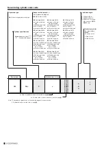
1.
For mounting position and moving procedure of the
sensor switch, refer to
E
Page
F
.
2.
When an inductive load will be connected to reed sensor
switches or if capacitive surge will occur, take some
contact protection countermeasures. For contact
protection countermeasures, refer to Page
C
.
1.
Do not place your hands in the cylinder operating direction.
2.
In the initial operation, be cautious against cylinder operating direction.
3.
When the cylinder is retracting, be cautious against part of your body
not be caught in a gap between the cylinder body and the end plate.
4.
At the time of maintenance, be sure to check that there is no
residual pressure within the cylinder before performing the work.
5.
The cylinder speed should be 500 mm/s or less when using
the cylinder. However, even within the allowable range, if the
speed and load are large, install an external stopper to avoid
applying direct impact to the cylinder.
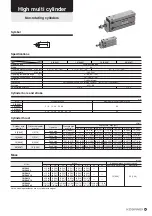
6.
Use the cylinder at the value below the allowable kinetic
energy shown in the following table.
Kinetic energy of load is calculated using the following formula.
Ex =
m
2
v
2
Ex: Kinetic energy (J)
m: Mass of load (kg)
v: Piston speed (m/s)
Cylinder bore
mm [in.]
6 [0.236]
10 [0.394]
16 [0.630]
20 [0.787]
Allowable kinetic energy
J [in · lbf]
0.007 [0.062]
0.018 [0.159]
0.031[0.274]
0.044 [0.389]
Connecting thread
M3
×
0.5
M5
×
0.8
Tightening torque N · m [in · lbf]
0.29 [2.57]
1.37 [12.13]
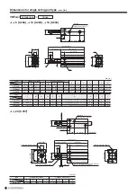
Model
YMDA
(Double acting type)
YMSA
(Single acting push type)
YMTA
(Single acting pull type)
YMDAL
(Non-rotating double acting type)
φ
D (mm [in.])
6 [0.236]
10 [0.394]
16 [0.630]
20 [0.787]
6 [0.236]
10 [0.394]
16 [0.630]
20 [0.787]
6 [0.236]
10 [0.394]
16 [0.630]
20 [0.787]
6 [0.236]
10 [0.394]
16 [0.630]
20 [0.787]
R
2
(mm [in.])
9.0 [0.354]
10.0 [0.394]
11.5 [0.453]
14.5 [0.571]
17.5 [0.689]
20.0 [0.787]
21.0 [0.827]
24.5 [0.965]
9.0 [0.354]
11.0 [0.433]
11.5 [0.453]
14.5 [0.571]
9.0 [0.354]
10.0 [0.394]
12.0 [0.472]
14.5 [0.571]
R
(mm [in.])
25.0 [0.984]
28.0 [1.102]
29.5 [1.161]
33.5 [1.319]
21.5 [0.846]
23.0 [0.906]
25.0 [0.984]
28.5 [1.122]
25.0 [0.984]
28.0 [1.102]
29.5 [1.161]
33.5 [1.319]
25.0 [0.984]
33.0 [1.299]
34.5 [1.358]
43.5 [1.713]
R (N [lbf.])
0.99 [0.223]
2.75 [0.618]
7.04 [1.583]
10.99 [2.471]
0.74 [0.166]
2.27 [0.510]
5.97 [1.342]
10.05 [2.259]
0.50 [0.112]
1.58 [0.355]
4.95 [1.113]
7.29 [1.639]
0.99 [0.223]
2.75 [0.618]
7.04 [1.583]
10.99 [2.471]
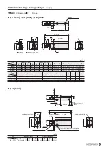
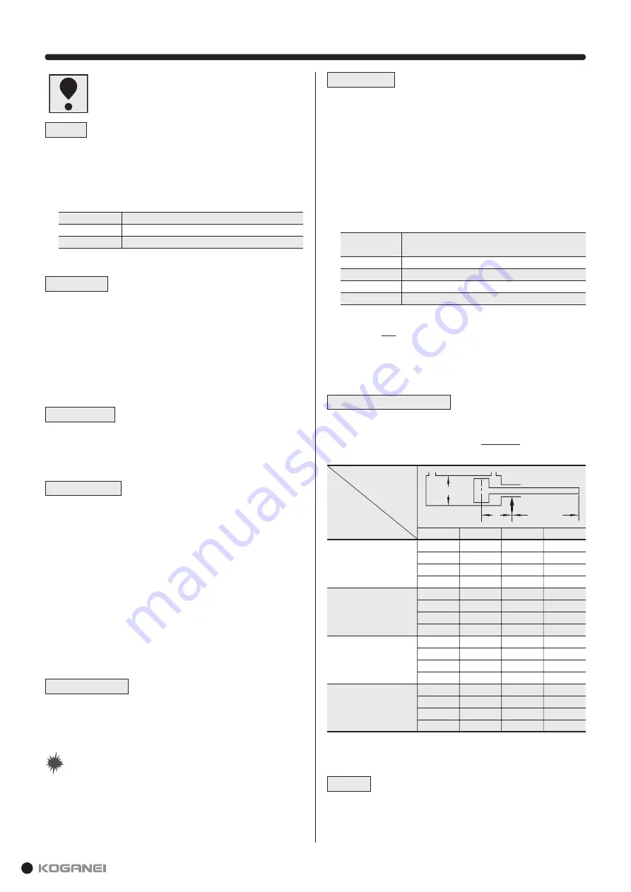
Dimensions
Note: In the case of sensor cylinder, use the value
R
2
shown in the table by
adding the value shown below as new
R
2
for calculating maximum
allowable lateral lead.
φ
6 [0.236] to
φ
16 [0.630]:
+
5 [0.197],
φ
20 [0.787]:
+
10 [0.394]
W
≤
·
R
R
2
R
1
+
R
2
R
2
R
1
= (
R
+St)
φ
D
R
Allowable lateral load
Use the cylinder under the condition below the following maximum
allowable lateral load.
Based on JIS Standard B8377 "Pneumatic cylinder"
Maximum allowable lateral load
Summary of Contents for YMDA Series
Page 34: ...33 MEMO ...


