8
Handling Instructions and Precautions
Mounting
1.
Any mounting posture is available but the mounting surface
should be flat surface. Occurrence of twist or bending when in
installation could not only deteriorate the accuracy but also
cause air leakage or defective operations.
2.
Take caution that scratched or dented mounting surface of the
cylinder may deteriorate the flatness.
3.
When the impact is too large, be sure to install some support
bracket on the cylinder in addition to mounting screws.
4.
Ensure to keep enough strength for the cylinder and
mounting screws.
5.
When the screws may be loosened by the impact or vibration,
take measures against screw loosening.
6.
The sliding portion of the piston rod should not be scratched
or dented. Scratched or dented sliding portion could damage
seals and cause air leakage.
7.
Do not wipe out the grease applied on the piston rod and
linear guide. This may cause the product to defective
operation. If oil cannot be found, apply grease to them.
(Grease: Universal type Lithium based grease No. 2)
8.
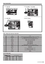
To tighten the cylinder, use the following tightening torque.
When using female threads of the main body for mounting,
tighten the screw under the tightening torque shown in ( ).
Mounting
Avoid the following usages.
9.
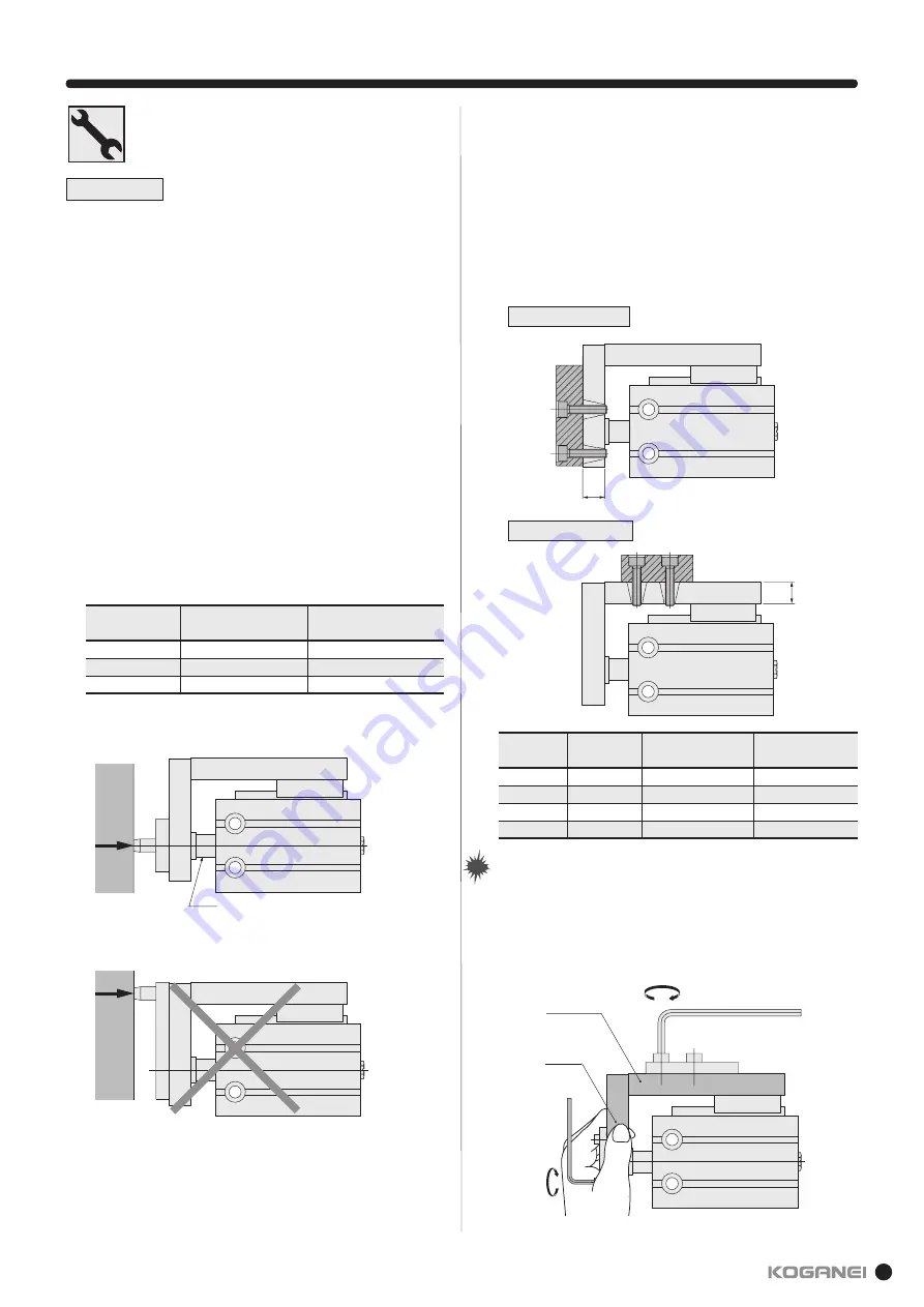
When thrust of a cylinder with guide directly apply to the plate,
apply the force to the rod axis center.
Cylinder bore
mm [in.]
6 [0.236] · 10 [0.394]
16 [0.630]
20 [0.787]
M3
×
0.5
M4
×
0.7
M5
×
0.8
1.08 [9.56] (0.59 [5.22])
2.45 [21.68] (1.37 [12.13])
5.10 [45.14] (2.84 [25.14])
Screw size
Tightening torque
N · m [in · lbf]
Rod
10. Mounting of workpiece
For the cylinder with guide, a workpiece can be mounted on
two surfaces.
To tighten screws for mounting a workpiece, tighten at a
torque within its limited range.
1.
As the plate table is supported by the linear guide, do not
apply strong impact or excessive moment to it when
mounting a workpiece.
2.
When securing a workpiece in a plate table with screws,
hold the table to tighten screws. Tightening with the body
held may apply excessive moment to the guide portion,
causing deteriorating the accuracy.
Cylinder bore
mm [in.]
0
6 [0.236]
10 [0.394]
16 [0.63]
20 [0.787]
M3
×
0.5
M3
×
0.5
M4
×
0.7
M5
×
0.8
0.59 [5.22]
0.59 [5.22]
1.37 [12.13]
2.84 [25.14]
5 [0.197]
6 [0.236]
8 [0.315]
10 [0.394]
Screw size
Maximum tightening torque
N · m [in · lbf]
H
mm [in.]
Front surface mounting
H
Upper surface mounting
H
Table
Plate
Note
Note
Summary of Contents for YMDA Series
Page 34: ...33 MEMO ...


