TP-6073 4/06
34
Section 6 Controller Troubleshooting
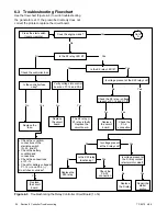
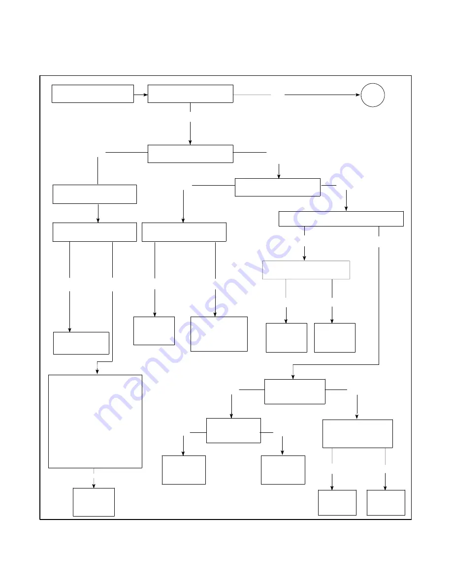
6.3 Troubleshooting Flowchart
Use the flow chart (Figure 6-3) to aid in troubleshooting
the generator set. If the prescribed remedy does not
correct the problem, replace the circuit board.
S
Check the condition/
connections of the
start/stop switch
(N, 43, and 47).
S
Check the battery
condition and
connections.
S
Check the connections
at P1--14.
S
Check for battery voltage at
P1-14 (+) and P2-4 (--).
Do all check out okay?
Is the controller fuse
okay?
Replace the
fuse.
Press the start switch
(local or remote).
Does the engine crank?
Yes
No
Is the K2 relay LED lit?
No
Is the K3 relay LED lit?
Yes
No
Yes
No
Verify voltage into control
board on P1-14 and P2-4.
No
Yes
Replace
the circuit
board.
The K3 relay or
K1 relay is faulty.
Replace the
circuit board.
Is voltage present
at the S relay coil?
Yes
Is the K20 relay
functioning?
Is voltage present at
the S relay contact
(starter motor side)?
No
Yes
Replace
the S relay.
Repair the
starter
motor.
Replace the
K20 relay.
Check the
P4--22
connection.
Is voltage present at the K20 relay coil?
Yes
Check the K3 relay—voltage
present at P1-14 and P1-9?
No
Replace
the circuit
board.
No
Yes
Check the
P1--4
connection.
No
Yes
No
Yes
Check the controller fuse.
Go to
A
Yes
Replace
the circuit
board.
Figure 6-3
Troubleshooting the Relay Controller Circuit Board (1 of 4)
Summary of Contents for 10EOR
Page 10: ...10 Safety Precautions and Instructions TP 6073 4 06 Notes...
Page 12: ...TP 6073 4 06 12 Service Assistance Notes...
Page 22: ...TP 6073 4 06 22 Section 3 Intake and Exhaust System Notes...
Page 26: ...TP 6073 4 06 26 Section 4 Fuel System Notes...
Page 30: ...TP 6073 4 06 30 Section 5 Cooling System Notes...
Page 38: ...TP 6073 4 06 38 Section 6 Controller Troubleshooting Notes...
Page 54: ...TP 6073 4 06 54 Section 8 Component Troubleshooting Notes...
Page 60: ...TP 6073 4 06 60 Section 9 Generator Disassembly Reassembly Notes...
Page 82: ...TP 6073 4 06 82...
Page 83: ...TP 6073 4 06 83...


