background image

TP-6073 4/06

73

Section 10 Wiring Diagrams

4

3

2

1

Stator Leads

L0

GRD.

L2

L1

L0 (Neutral)

Line
Side

Factory
Two-Pole
Circuit
Breaker

Ground

Load
Side

100-120/200-240 Volt,

3 Wire

60 Hz

50 Hz

L0-L1

100-120 Volt

100-120 Volt

L0-L2

100-120 Volt

100-120 Volt

L0-L2

200-240 Volt

200-240 Volt

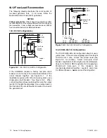
Figure 10-3

100-120/200-240 Volt
3-Wire Configuration

200-240 Volt Configurations

The 200-240 volt configuration does not use a jumper
lead. If the unit was originally wired for straight 100-120
volt, 3 wire, remove the jumper lead (see Figure 10-1 for
location).

4

3

2

1

Stator Leads

L0

GRD.

L1

L0 (Neutral)

Line
Side

Single-Pole
Circuit
Breaker

Ground

Load
Side

200-220-240 Volt

2 Wire

Tape to insulate
from ground

60 Hz

L0-L1

not used

200-220-240 Volt

50 Hz

Figure 10-4

200-220-240 Volt 2-Wire Configuration

10.13Twelve-Lead Reconnection

The reconnection procedure that follows details voltage
reconnections only.

If the generator set requires

frequency changes, adjust the governor and voltage
regulator. See the generator set service manual for
information regarding frequency adjustment.

In all cases, follow National Electrical Code (NEC)
guidelines.

Reconnect the stator leads of the generator set to
change output phase or voltage. Refer to the following
procedure and connection schematics. Follow all safety
precautions at the front of this manual and in the text
during reconnection procedure.

NOTICE

Voltage reconnection.

Affix a notice to the generator set after

reconnecting the set to a voltage different from the voltage on
the nameplate. Order voltage reconnection decal 246242
from an authorized service distributor/dealer.

Twelve-Lead Reconnection Procedure

1. Move generator set start/stop switch to the STOP

position.

2. Disconnect engine starting battery, negative (--)

lead first. Disconnect power to battery charger, if
equipped.

3. Use Figure 10-5 to determine generator set

voltage configuration. Note original voltage and
reconnect as needed.

Summary of Contents for 10EOR

Page 1: ...Commercial Recreational Mobile Generator Sets Models 7 5EOR EORZ 10EOR EORZ 15EOR EORZ 20EOR EORZ 6EFOR EFORZ 9EFOR EFORZ 12 5EFOR EFORZ 16 5EFOR EFORZ TP 6073 4 06a Service...

Page 2: ...y available for future reference Record field installed kit numbers after installing the kits Generator Set Identification Numbers Record the product identification numbers from the generator set name...

Page 3: ...3 Fuel System Bleeding 24 4 4 Governor 25 Section 5 Cooling System 27 5 1 General 27 5 2 Cooling System 27 5 2 1 Coolant Level Check 27 5 2 2 Cooling System Component Inspection 27 5 2 3 Procedure to...

Page 4: ...nd Four Meter Panel 63 10 4 7 5 10EOR 6 9EFOR with Brushes Schematic Wiring Diagram 64 10 5 7 5 10EOR 6 9EFOR with Brushes Point to Point Wiring Diagram 65 10 6 7 5 10EORZ 6 9EFORZ with Exciter Schema...

Page 5: ...cting the battery Follow these precautions to prevent the starting of the generator set by the remote start stop switch Battery Sulfuric acid in batteries Can cause severe injury or death Wear protect...

Page 6: ...ustfumes when working on or near the generator set Never operate the generator set inside a building unless the exhaust gas is piped safely outside Never operate the generator set where exhaust gas co...

Page 7: ...erty damage Connect the generator set to the building s electrical system only through an approved device and after the building s main switch is opened WARNING Grounding electrical equipment Hazardou...

Page 8: ...ion Combustible materials Fire can cause severe injury or death A hot exhaust system can ignite adjacent combustible materials Do not locate electrical wiring fuel lines or combustible materials above...

Page 9: ...itute with inferior grade hardware Screws and nuts are available in different hardness ratings To indicate hardness American Standard hardware uses a series of markings and metric hardware uses a nume...

Page 10: ...10 Safety Precautions and Instructions TP 6073 4 06 Notes...

Page 11: ...ep equipment in top condition x in 001 002 a Service Assistance For professional advice on generator power requirements and conscientious service please contact your nearest Kohler distributor or deal...

Page 12: ...TP 6073 4 06 12 Service Assistance Notes...

Page 13: ...h 12 Overflow tube 13 Pressure cap 14 Fuel injection pump 15 Low oil pressure safety shutdown switch 16 Radiator 17 Coolant drain 18 Fuel filter 19 Oil drain 20 Fuel pump 21 Oil filter 22 Fuel inlet c...

Page 14: ...High water temperature safety shutdown switch 10 Oil fill 11 Pressure cap 12 Overflow tube 13 Fuel injection pump 14 Radiator 15 Coolant drain 16 Oil drain 17 Fuel pump 18 Oil filter 19 Fuel inlet con...

Page 15: ...ed ductile iron casting Heat treated ductile iron casting Main bearings number type 2 replaceable sleeve 2 replaceable sleeve 2 replaceable sleeve 2 replaceable sleeve Injection pump Yanmar YPES Yanma...

Page 16: ...ps 19 0 9 12 0 8 8 1 4 8 1 4 Full load 60 Hz volts amps 32 1 5 33 2 2 16 2 4 16 2 4 Exciter field resistance cold ohms 4 8 4 8 5 8 5 8 Exciter armature resistance cold ohms 1 2 1 2 0 5 0 5 Stator outp...

Page 17: ...set when it is operating Exposed moving parts can cause severe injury or death Keep hands feet hair clothing and test leads away from the belts and pulleys when the generator set is running Replace gu...

Page 18: ...Rotating parts Can cause severe injury or death Do not operate generator set without all guards screens and covers in place WARNING Exposed moving parts can cause severe injury or death Keep hands fee...

Page 19: ...ry connections prevent generator set starting Sulfuric acid in batteries Can cause severe injury or death Wear protective goggles and clothing Battery acid may cause blindness and burn skin WARNING Ba...

Page 20: ...he generator set for 30 minutes to redistribute added coolant x sm 002 003 2 6 3 Fuel System Prepare the fuel system for storage as follows Diesel Fueled Engines 1 Fill the fuel tank with 2 diesel fue...

Page 21: ...the STOP position 11 Reconnect the generator set engine starting battery negative lead last 12 Reconnect the power to the battery charger if equipped 3 2 Exhaust System Inspection Carbon monoxide Can...

Page 22: ...TP 6073 4 06 22 Section 3 Intake and Exhaust System Notes...

Page 23: ...fuel filter See Figure 4 1 or Figure 4 2 Fuel Filter Service Procedure Note The procedures to disable and enable the generator set apply to both spin on filters and fuel filter elements Disable the G...

Page 24: ...ne generator to start To prevent starting toggle the start stop switch by momentarily placing the start stop switch in the START position for a few seconds and then placing the switch in the STOP posi...

Page 25: ...ntered or if poor governor control develops after extended usage 60 Hz generator sets are designed to operate at 60 63 Hz 1800 rpm under full load and 1890 rpm under no load 50 Hz generator sets are d...

Page 26: ...TP 6073 4 06 26 Section 4 Fuel System Notes...

Page 27: ...system to prevent overheating and subsequent engine damage Note Block heater damage The block heater will fail if the energized heater element is not immersed in coolant Fill the cooling system before...

Page 28: ...of the radiator has mineral deposits or the used coolant contains dirt or grease refer to Section 5 2 4 Procedure to Flush and Clean the Cooling System If the cooling system does not have mineral depo...

Page 29: ...freezing and overheating protection A coolant solution containing more than 50 ethylene glycol can cause engine or component damage Do not use alcohol or methanol antifreeze or mix them with the speci...

Page 30: ...TP 6073 4 06 30 Section 5 Cooling System Notes...

Page 31: ...oid to complete the conditions necessary for engine startup Releasing the start stop switch allows the switch to return to its neutral position If the start stop switch is released before the engine s...

Page 32: ...as two switches that monitor critical operating conditions D The High Engine Temperature HET switch closes when engine coolant temperature approaches an unsafe level D The Low Oil Pressure LOP switch...

Page 33: ...ime delay relay K5 5 LED5 6 LED2 7 Engine run relay K2 8 AC crank disconnect relay K1 9 LED1 10 Fault shutdown relay K4 11 Relay schematic 12 LED4 13 LED3 Figure 6 1 Controller Circuit Board H 239563...

Page 34: ...Yes No Is the K2 relay LED lit No Is the K3 relay LED lit Yes No Yes No Verify voltage into control board on P1 14 and P2 4 No Yes Replace the circuit board The K3 relay or K1 relay is faulty Replace...

Page 35: ...fuse BCA functional Does unit have fuel No Yes Engine fault check the fuel supply fuel feed pump fuel injection pump etc No Replace the fuse Yes Is the K25 relay functional No Replace the K25 relay Y...

Page 36: ...solenoid No No Replace the circuit board inoperative K5 relay Is the low oil pressure LOP safety shutdown switch functional No Replace the LOP safety shutdown switch Yes No Did the K4 relay LED light...

Page 37: ...r field Yes Test the stator and main field rotor No No Separately excite the generator set to determine if other components are inoperative Replace the controller circuit board Yes No Test the voltage...

Page 38: ...TP 6073 4 06 38 Section 6 Controller Troubleshooting Notes...

Page 39: ...Short circuits Hazardous voltage current can cause severe injury or death Short circuits can cause bodily injury and or equipment damage Do not contact electrical connections with tools or jewelry wh...

Page 40: ...3 Terminal P10 2 4 10 amp fuse 5 DC ammeter 6 12 volt battery DC 7 Brushes 8 Collector rings 9 Main field rotor 10 Jumper lead 11 Engine ground Figure 7 2 Separate Excitation Connections Brushed Unit...

Page 41: ...r Test Procedure 1 Connect the components as shown in Figure 7 5 2 Turn the variable transformer setting to zero Plug in the variable transformer 3 Turn the variable transformer on Slowly increase the...

Page 42: ...o test the voltage regulator D Step up transformer 1 2 120 volts to 240 volts 1 0 amp minimum D Lamp 250 volt 100 watt D AC voltmeter 250 volt minimum D Fuse 1 amp D Switch 1 single pole single throw...

Page 43: ...the generator output Stability Potentiometer fine tunes the regulator circuitry to reduce light flicker Volts Hz Potentiometer determines the engine speed Hz at which the generator output begins to d...

Page 44: ...ncy meter The factory setting is 57 5 58 Hz for 60 Hz models and 47 5 48 Hz for 50 Hz models 7 Rotate the volts Hz potentiometer clockwise until the voltage level as measured on the voltmeter begins t...

Page 45: ...will cause the brush to wear evenly The brushes must ride 100 on the collector rings or arcing will occur and cause burned rings or failure of the voltage regulator Figure 7 11 shows the correct posit...

Page 46: ...Repair or replace the exciter field if the ohmmeter readings indicate a inoperative exciter field Refer to Section 9 for removal If the resistance test is inconclusive perform a megohmmeter test on th...

Page 47: ...for the armature resistance No continuity indicates an open armature winding If the resistance test is inconclusive perform a megohmmeter test on the exciter armature as described in the next step Not...

Page 48: ...d F and F leads See Figure 7 18 See Section 1 3 for the resistance reading A low reading indicates an internal short and a high reading indicates an open winding Repair or replace the main field if th...

Page 49: ...nerator set engine starting battery negative lead first 3 Check the generator output lead connections See the installation manual for voltage reconnection and Section 10 of this manual for the wiring...

Page 50: ...3 and Figure 7 24 Apply 500 volts DC to any stator lead from each winding and the stator frame Follow the megohmmeter manufacturer s instructions for using the megohmmeter Repeat the test on the other...

Page 51: ...ning batteries to prevent accumulation of explosive gases With the generator set battery connected check the wiring harness and some generator set components with a voltmeter as described in Figure 8...

Page 52: ...wiring Starter solenoid S relay P4 22 and battery cable NOTE Disconnect J4 and P4 to perform this test Ohmmeter on R x 1 scale If functional approx 0 20 0 35 ohms at 27_C 80_F Controller 15 amp fuse a...

Page 53: ...r desired resistance values 2 Meter and 4 Meter Panels Temperature Resistance 60_C 140_F 90_C 194_F 100_C 212_F 134 0 10 ohms 51 5 4 ohms 38 0 3 ohms Figure 8 3 Water Temperature Sender Resistance 2 M...

Page 54: ...TP 6073 4 06 54 Section 8 Component Troubleshooting Notes...

Page 55: ...e generator set See Figure 9 1 HP 250000D E 1 1 Generator set end panel Figure 9 1 End Panel 5 Remove the six screws and lift off the controller cover 6 Disconnect the P4 22 pin connector from J4 and...

Page 56: ...the retaining bolt and washer d Remove the armature from the shaft guiding the rotor leads through the armature bores See Figure 9 5 16 Remove the tie wraps and disconnect the P5 33 44 55 F1 and F2 w...

Page 57: ...tor Remove or rotate the fan guard if necessary to clear the vibromounts 24 Remove the eight fan bolts and remove the fan and fan spacer See Figure 9 8 25 Remove the eight drive disc bolts to remove t...

Page 58: ...erbolts 7 5 kW models the two long bolts in the lower holes Check that the alignment marks on the stator housing and locator plate match See Figure 9 11 Tighten the overbolts to 34 Nm 25 ft lbs 558861...

Page 59: ...ox to the generator set with the original mounting hardware Connect the stator leads to the circuit breaker and neutral stud LO as marked during disassembly Note Check the generator set s nameplate to...

Page 60: ...TP 6073 4 06 60 Section 9 Generator Disassembly Reassembly Notes...

Page 61: ...ause theseconditions increasethe riskof electrocution Accidental starting Can cause severe injury or death Disconnect the battery cables before working on the generator set Remove the negative lead fi...

Page 62: ...Start Stop Stop 10 amp fuse P3 4 J3 4 J3 5 J3 1 J3 6 TP 5588 7 10 2 Remote Start and Two Meter Panel P3 2 J3 2 Start P P 7C K1 70 47 43 N Oil pressure gauge Water temp gauge Gen ON light Remote switch...

Page 63: ...Oil pressure gauge Water temp gauge Gen ON light Remote switch 5 P3 5 P3 6 P3 1 P3 2 P3 3 P2 3 P2 7 P2 8 P2 9 P4 2 P4 3 K2 P1 14 47 P2 4 43 P2 5 P2 6 N P1 9 N Relay circuit board Local switch Violet T...

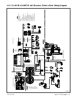
Page 64: ...TP 6073 4 06 64 Section 10 Wiring Diagrams 10 4 7 5 10EOR 6 9EFOR with Brushes Schematic Wiring Diagram GM10486B B...

Page 65: ...TP 6073 4 06 65 Section 10 Wiring Diagrams 10 5 7 5 10EOR 6 9EFOR with Brushes Point to Point Wiring Diagram GM10486A B...

Page 66: ...TP 6073 4 06 66 Section 10 Wiring Diagrams 10 6 7 5 10EORZ 6 9EFORZ with Exciter Schematic Wiring Diagram GM11416B B...

Page 67: ...TP 6073 4 06 67 Section 10 Wiring Diagrams 10 7 7 5 10EORZ 6 9EFORZ with Exciter Point to Point Wiring Diagram GM11416A B...

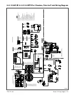
Page 68: ...TP 6073 4 06 68 Section 10 Wiring Diagrams 10 8 15 20EOR 12 5 16 5EFOR with Brushes Schematic Wiring Diagram 363508B C...

Page 69: ...TP 6073 4 06 69 Section 10 Wiring Diagrams 10 9 15 20EOR 12 5 16 5EFOR w Brushes Point to Point Wiring Diagram 363508A C...

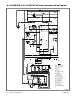
Page 70: ...TP 6073 4 06 70 Section 10 Wiring Diagrams 10 1015 20EORZ 12 5 16 5EFORZ w Exciter Schematic Wiring Diagram 363509B B...

Page 71: ...TP 6073 4 06 71 Section 10 Wiring Diagrams 10 1115 20EORZ 12 5 16 5EFORZ w Exciter Point to Point Wiring Diagram 363509A B...

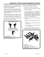
Page 72: ...s a 100 120 volt 2 wire system use a single pole circuit breaker See Figure 10 2 When connecting stator phase leads together size the output lead L1 to handle the amperage Use a jumper lead on the lin...

Page 73: ...s details voltage reconnections only If the generator set requires frequency changes adjust the governor and voltage regulator See the generator set service manual for information regarding frequency...

Page 74: ...Tmarktowardthegeneratorset Somegeneratorsetshave no current transformers Note Phase Rotation A L1 B L2 and C L3 Note All 12 lead generator sets are reconnectable The 6 lead 600 volt generator set is n...

Page 75: ...led cyl cylinder D A digital to analog DAC digital to analog converter dB decibel dBA decibel A weighted DC direct current DCR direct current resistance deg degree dept department dia diameter DI EO d...

Page 76: ...OS oversize overspeed OSHA Occupational Safety and Health Administration OV overvoltage oz ounce p pp page pages PC personal computer PCB printed circuit board pF picofarad PF power factor ph phase PH...

Page 77: ...low top of nut Figure 1 Acceptable Bolt Lengths Steps for common hardware application 1 Determine entry hole type round or slotted 2 Determine exit hole type fixed female thread weld nut round or slot...

Page 78: ...27 7 16 14 ft lbs Nm 29 39 44 60 63 85 7 16 20 ft lbs Nm 32 43 50 68 70 95 1 2 13 ft lbs Nm 44 60 68 92 96 130 1 2 20 ft lbs Nm 49 66 76 103 108 146 9 16 12 ft lbs Nm 60 81 98 133 138 187 9 16 18 ft l...

Page 79: ...al External Tooth Lock Hardness Grades American Standard Grade 2 Grade 5 Grade 8 Grade 8 9 Hex Socket Head Metric Number stamped on hardware 5 8 shown 5 8 Allent head screw is a trademark of Holo Krom...

Page 80: ...6024 2 7 16 14 x 1 00 X 6024 8 7 16 14 x 1 25 X 6024 3 7 16 14 x 1 50 X 6024 4 7 16 14 x 2 00 X 6024 11 7 16 14 x 2 75 X 6024 12 7 16 14 x 6 50 X 129 15 1 2 13 x 75 X 129 17 1 2 13 x 1 00 X 129 18 1 2...

Page 81: ...25 x 20 M933 10020 60 M10 1 50 x 20 M933 10025 60 M10 1 50 x 25 M933 10030 60 M10 1 50 x 30 M933 10030 82 M10 1 50 x 30 M961 10035 60 M10 1 25 x 35 M933 10035 60 M10 1 50 x 35 M933 12016 60 M12 1 75...

Page 82: ...TP 6073 4 06 82...

Page 83: ...TP 6073 4 06 83...

Page 84: ...ler Wisconsin 53044 Phone 920 565 3381 Fax 920 459 1646 For the nearest sales service outlet in the US and Canada phone 1 800 544 2444 KohlerPowerSystems com Kohler Power Systems Asia Pacific Headquar...

Reviews: