TP-6196 10/09
22
Section 2 Scheduled Maintenance
2.
Replace the oil filter.
a. Remove
the
oil
filter
by
rotating
it
counterclockwise with an oil filter wrench.
b. Apply a light coat of clean oil to the rubber seal
of the new oil filter.
c. Install the new oil filter following the instructions
provided with the filter.
Note:
Dispose of all waste materials (engine
oil, fuel, filter, etc.) in an environmentally
safe manner.
3.
Fill with oil.
a. Fill with oil. See Section 2.2.3 for oil selection
and Figure 2-3 for oil capacity.
b. Replace the oil fill cap and dipstick.
4.
Check for leaks.
a. Check that the generator set master switch is in
the OFF position.
b. Reconnect the generator set engine starting
battery, negative (--) lead last.
c. Reconnect the power to the battery charger.
d. Start the generator set and check for leaks
around the oil filter.
e. Stop the generator set and tighten the oil filter to
stop any leaks.
f. Reinstall the housing side panel.
2.2.5
Oil Cooler
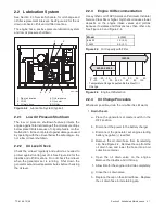
Inspect and clean the oil cooler at the intervals shown in
the Service Schedule. The oil cooler must be kept free
of debris.
See Figure 2-2 and Figure 2-5 for the oil cooler location.
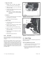
Clean the outside of the oil cooler with a brush or
compressed air. If it is necessary to clean the back of the
oil cooler, remove the two screws holding the oil cooler
unit to the blower hosing. Tilt the cooler and clean with a
brush or compressed air as shown in Figure 2-6. After
cleaning, reinstall the oil cooler and secure with the
mounting screws.
2
24 590 01--A
1. Oil filter
2. Oil cooler
1
Figure 2-5
Oil Cooler Location
24 590 01--A
Figure 2-6
Cleaning the Oil Cooler
2.3 Spark Plugs
Reset the spark plug gap or replace the plugs with new
plugs as necessary.
Spark Plug Maintenance Procedure
1. Clean the area around the base of the spark plug to
keep dirt and debris out of the engine.
2. Remove the spark plug and check its condition.
Replace the spark plug if it is worn or if its reuse is
questionable.
Summary of Contents for 12RES
Page 2: ......
Page 6: ...TP 6196 10 09 6 Notes ...
Page 34: ...TP 6196 10 09 34 Section 3 Troubleshooting Notes ...
Page 52: ...TP 6196 10 09 52 Section 4 ADC 2100 and DC 2200 Controllers Notes ...
Page 72: ...TP 6196 10 09 72 Section 5 ADC RES and DC RET Controller Notes ...
Page 100: ...TP 6196 10 09 100 Section 6 Component Testing and Adjustment Notes ...
Page 131: ......


