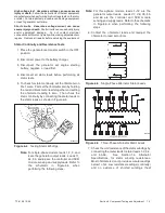
TP-6196 10/09
81
Section 6 Component Testing and Adjustment
6.7.3
Volts per Hertz (Hz) Adjustments
(Droop)
When the frequency falls below the cut-in frequency
(see Figure 6-13), output voltage is reduced to relieve
the engine. The magnitude of the voltage reduction is
set by the 3P parameter. Monitor engine speed and
output voltage as loads are applied.
!
If there is excessive droop in engine speed and little
droop in voltage, increase the 3P value.
!
If there is little engine speed droop but excessive
voltage droop, decrease the 3P value.
!
Readjust the voltage stability (2P) and voltage (1P)
parameters after adjusting the 3P
setting, if
necessary. See the instructions in Section NO TAG.
!
Remember to save your settings.
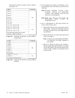
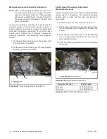
Each step of 3P changes the amount of voltage droop
approximately 0.5% of system voltage for each cycle
(Hz) below the cut-in frequency. See Figure 6-15.
3P
Voltage Droop, % of System Voltage per
1 Hz Cycle Below Cut--In Frequency
0
0
1
0.5%
2
1.0%
3
1.5%
4
2.0%
5
2.5%
6
3.0%
7
3.5%
8
4.0%
9
4.5%
Figure 6-15
Voltage Droop Adjustments
6.7.4
Voltage Connections,
Single-Phase
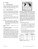
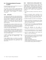
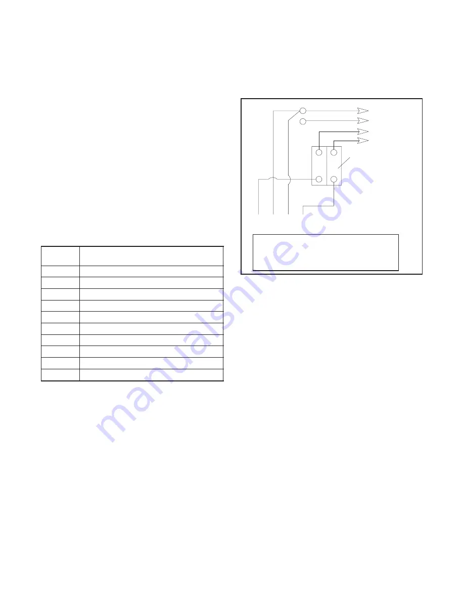
Single-phase generator sets are available from the
factory connected for 110/220 volt 50 Hz or 120/240 volt
60 Hz. See Figure 6-16 for the factory connections.
These generator sets are not reconnectable.
4
3
2
1
Stator Leads
LO
GRD
L2
L1
LO (Neutral)
Line
Side
Factory two-pole
circuit breaker
Ground
Load
Side
TP-5867
L0-L1
L0-L2
L1-L2
60 Hz
120 volt
120 volt
240 volt
50 Hz
110 volt
110 volt
220 volt
Figure 6-16
110/220 and 120/240 Volt, 3-Wire
Configurations
Summary of Contents for 12RES
Page 2: ......
Page 6: ...TP 6196 10 09 6 Notes ...
Page 34: ...TP 6196 10 09 34 Section 3 Troubleshooting Notes ...
Page 52: ...TP 6196 10 09 52 Section 4 ADC 2100 and DC 2200 Controllers Notes ...
Page 72: ...TP 6196 10 09 72 Section 5 ADC RES and DC RET Controller Notes ...
Page 100: ...TP 6196 10 09 100 Section 6 Component Testing and Adjustment Notes ...
Page 131: ......


