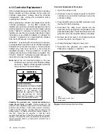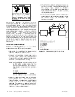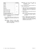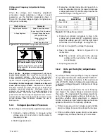
TP-6735 7/17
57
Section 4 Controller
Replace the Controller
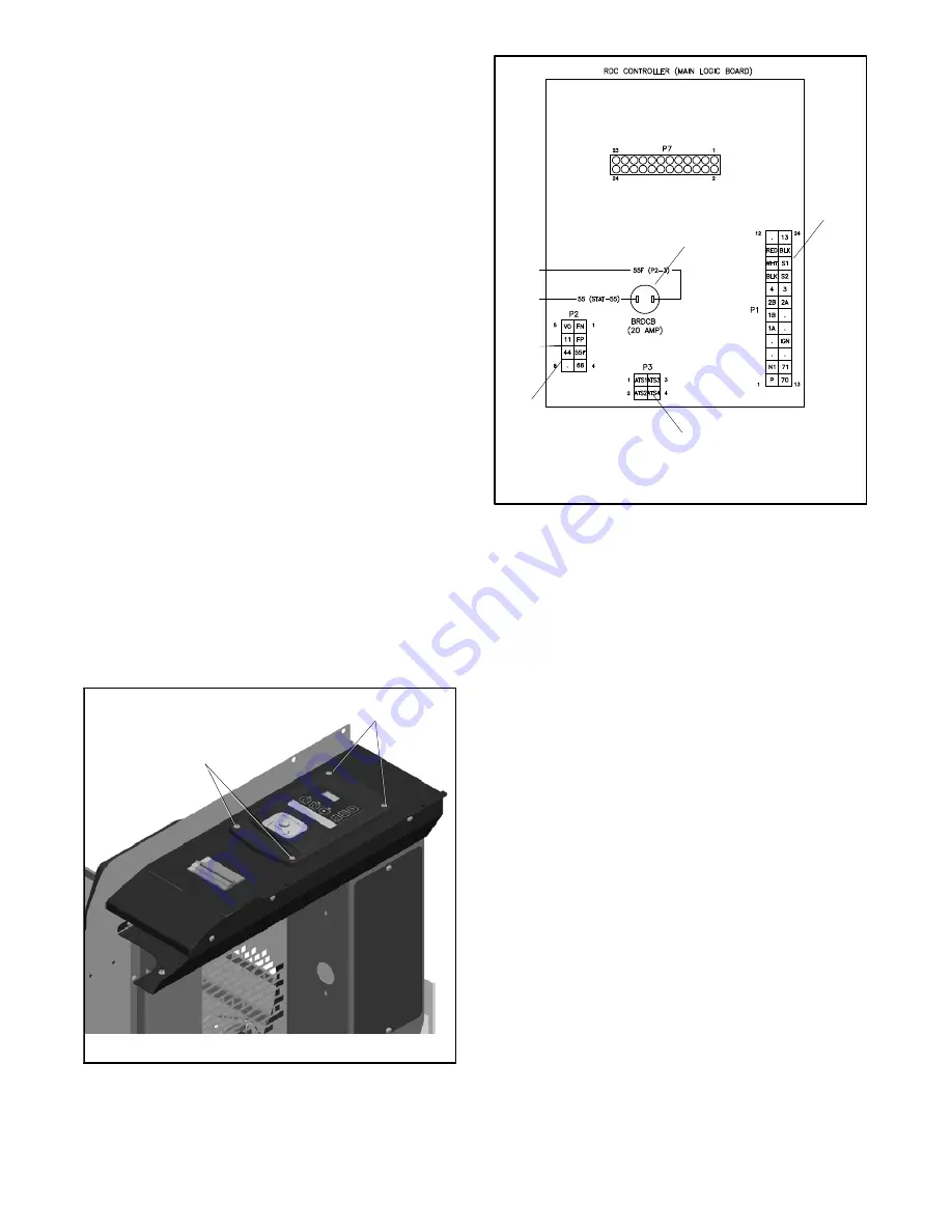
8. Remove the four (4) screws securing the controller
and
carefully
lift the controller. See Figure 4-17.
Note:
Be careful of the leads and harness
connected to the controller.
9. Note the connections on the back of the controller,
and then disconnect P1, P2, P3, and leads 55 and
55F at the miniature circuit breaker.
See
Figure 4-18 or the wiring diagram.
10. Remove the old controller.
11. Reconnect P1, P2 and P3 to the new controller
assembly GM62863-2 or GM62863-3. Connect
leads 55 and 55F to the mini-breaker.
12. Mount the new controller assembly onto the
junction box using the four (4) screws removed in
step 8.
13. Reconnect the engine starting battery, negative (--)
lead last.
14. Reconnect the utility power to the generator set by
closing the circuit breaker in the essential loads
panel.
15. Plug the battery charger cord into the receptacle on
the generator set.
16. Replace the air intake end panel and secure with
two screws.
GM66569
1. Controller screws (qty. 4)
1
1
Figure 4-17
Controller Mounting Screws
1
GM69754
1. P1
2. P3
3. P2
4. 20 amp mini breaker
2
3
4
Figure 4-18
Controller Connections
Configure the Controller
17. Configure the controller.
Choose one of the
following options:
a. Use the RDC controller keypad to set the new
controller’s voltage/frequency setting (Uu) and
engine configuration setting (Ec).
See
Section 4.10
and
TP-6733,
Installation
Manual.
b. If a settings file for the controller is available,
use a personal computer with Kohler
r
SiteTech
t
software to load the settings onto
the new controller. See TP-6701, SiteTech
Software Operation manual, for instructions.
c. Use a personal computer with SiteTech
software to set the following parameters. See
Section 4.10.5 and TP-6701, SiteTech
Software Operation Manual.
D
Genset Model Number (14RESL or 20RESL)
D
Engine Model Number (enter CH--740 for the
14RESL or CH--1000 for the 20RESL)
D
Voltage (240)
D
Frequency (60 Hz)
D
Number of phases (Single phase)
Summary of Contents for 14RES
Page 2: ......
Page 6: ...TP 6735 7 17 6...
Page 16: ...TP 6735 7 17 16 Section 1 Specifications Notes...
Page 102: ...TP 6735 7 17 102 Section 6 Disassembly Reassembly Notes...
Page 108: ...TP 6735 7 17 108 Section 7 Wiring Diagrams Notes...
Page 120: ...TP 6735 7 17 120 Notes...
Page 121: ...TP 6735 7 17 121 Notes...
Page 122: ...TP 6735 7 17 122 Notes...
Page 123: ......


