background image

TP-6735 7/17

68 Section 5 Component Testing and Adjustment

D

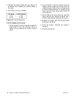
Readjust the voltage stability (2P) and voltage (1P)

parameters after adjusting the volts/Hz setting, if

necessary.

D

Remember to save your settings.

Frequency

Cut-In Frequency

60 Hz

57.5 Hz

50 Hz

47.5 Hz

Figure 5-14

Cut-In Frequencies

Volts/Hz Adjustment Procedure

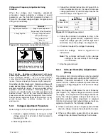
1. Set the voltmeter to measure frequency. Adjust the

engine speed to the cut-in frequency shown in

Figure 5-14 by adjusting the engine governor

speed.

2. Set the voltmeter to measure voltage. Adjust the

volts/Hz until the voltage level measured by the

voltmeter begins to drop. When set, the generator

(as load is applied) attempts to maintain normal

output until the engine speed drops below the

cut-in frequency.

3. Set the voltmeter to measure frequency. Adjust the

engine speed to the operating frequency (50 or

60 Hz) by adjusting the engine governor speed.

4. Readjust the voltage gain until the light flicker

minimizes, if necessary.

5. Check the voltage.

Readjust the voltage, if

necessary.

6. Stop the generator set.

Summary of Contents for 14RES

Page 1: ...Residential Commercial Generator Sets Models 14RES RESL 20RES RESL Controllers RDC Residential Digital Control DC Digital Control TP 6735 7 17c Service...

Page 2: ......

Page 3: ...gs 21 2 4 Air Cleaner Service 22 2 4 1 Air Cleaner 14RES RESL Models 22 2 4 2 Air Cleaner 20RES RESL Models 23 2 5 Cooling System 24 2 6 Exhaust System 24 2 7 Stepper Motor Coupling 24 2 8 Battery 25...

Page 4: ...Shutdown 46 4 8 6 Event History 46 4 9 Model RRT Transfer Switch Operation 50 4 9 1 Source Availability 50 4 9 2 ATS Control Sequence of Operation 50 4 9 3 Time Delays 50 4 9 4 Engine and Transfer Tim...

Page 5: ...tal Spark Advance Ignition DSAI Timing 78 5 11 3 Fuel Regulators 80 5 11 4 Fuel Conversion 20RES RESL 81 5 11 5 Fuel Conversion 14RES RESL 82 5 11 6 Fuel Metering Valve Adjustment 14RES RESL Only 83 5...

Page 6: ...TP 6735 7 17 6...

Page 7: ...the battery cables negative lead first Reconnect the negative lead last when reconnecting the battery Follow these precautions to prevent starting of the generator set by an automatic transfer switch...

Page 8: ...s or as recommended by the local fire code or an authorized agency Train all personnel on fire extinguisher operation and fire prevention procedures Exhaust System Carbon monoxide Can cause severe nau...

Page 9: ...and water solution with the fuel system test pressurized to at least 90 psi 621 kPa Do not use a soap solution containing either ammonia or chlorine because both prevent bubble formation A successful...

Page 10: ...surements of live circuits Use adequately rated test equipment with electrically insulated probes and follow the instructions of the test equipment manufacturer when performing voltage tests Observe t...

Page 11: ...to safe and efficient operation Inspect the parts often and perform required service at the prescribed intervals Maintenance work must be performed by appropriately skilled and suitably trained mainte...

Page 12: ...ada call the nearest regional office Headquarters Europe Middle East Africa EMEA Kohler Power Systems Netherlands B V Kristallaan 1 4761 ZC Zevenbergen The Netherlands Phone 31 168 331630 Fax 31 168 3...

Page 13: ...ith four cycle twin cylinder air cooled Kohler engines For engine service information and specifications not covered in this manual see the engine service manual See the List of Related Materials in t...

Page 14: ...nce ohms cold Single Phase Leads 1 2 3 4 0 06 0 02 11 44 0 13 0 04 55 66 0 60 0 44 Stator output voltage with separately excited rotor using 12 volt battery minimum Leads 1 2 3 4 105 V 88 V 11 44 210...

Page 15: ...heater not shown 9 Nameplate location 10 Gas regulator assembly 11 Fuel block or LP orifice location inside hose fitting 12 Muffler located below cover plate 13 Oil check dipstick 14 Governor assembly...

Page 16: ...TP 6735 7 17 16 Section 1 Specifications Notes...

Page 17: ...ibutor dealer perform generator set service Alternator Service Under normal operating conditions the generator set alternator does not require scheduled service Refer to the service schedule for items...

Page 18: ...e control system if equipped M Visible wear or damage Q Wire abrasions where subject to motion 6 months 6 months Wire cable insulation condition 3Y or 500 Engine and Mounting Visible wear or damage W...

Page 19: ...Engine Oil Recommendation Use 5W 30 API American Petroleum Institute Service Class SG SH or SJ synthetic oil Synthetic oil oxidizes and thickens less than other oils and leaves the engine intake valve...

Page 20: ...to the F mark on the dipstick 4 Check for leaks a Check for oil leaks b Fix leaks and recheck the oil level c Reinstall the housing side panel 2 2 5 Oil Cooler 14RES RESL Inspect and clean the oil co...

Page 21: ...with a brush or with compressed air 1 62 590 01 1 Oil cooler Figure 2 6 Oil Cooler Location 20RES RESL 2 3 Spark Plugs Reset the spark plug gap or replace the plugs with new plugs as necessary 1 Clea...

Page 22: ...with detergent Rinse the precleaner thoroughly until all traces of detergent are eliminated Squeeze out excess water do not wring Allow the precleaner to air dry 5 Saturate the precleaner with new en...

Page 23: ...loose or damaged air cleaner components could allow unfiltered air into the engine causing premature wear and failure Paper Element Service Replace the paper element at the intervals indicated in the...

Page 24: ...Exhaust System Remove all combustible materials from the exhaust location Combustible materials include building materials as well as natural surroundings Keep dry field grass foliage and combustible...

Page 25: ...event accumulation of explosive gases Battery short circuits Explosion can cause severe injury or death Short circuits can cause bodily injury and or equipment damage Disconnect the battery before gen...

Page 26: ...set until the engine stops 4 Press the OFF button on the controller 2 10 3 Cylinder Lubrication 1 Remove the spark plugs 2 Pour one tablespoon of engine oil into each spark plug hole Install the spar...

Page 27: ...the controller Section 4 10 contains the instructions for checking and changing the controller configuration D Inadequate fuel supply Check for damaged primary or secondary fuel regulators loose conne...

Page 28: ...o start to identify the cause of the blown fuse Lead 70A at the fuel valve Lead IGN at the ignition module Lead 71A at the starter relay Leads FP and FN at the rotor Repair or replace the component ca...

Page 29: ...clogged Check for a dirty air cleaner element Replace air cleaner element Check and replace air cleaner element at the intervals shown in the Service Schedule O M Magnetic pickup Check for 3 0 volts o...

Page 30: ...to instructions in the engine service manual Replace ignition components if necessary Engine S M Insufficient fuel pressure Check fuel pressure to the generator set Verify adequate fuel pressure and p...

Page 31: ...essure before performing test and or replacing LOP shutdown switch Engine S M Section 5 10 2 Fuel valve fuel regulator Check fuel valve connections Check regulator valve operation Check fuel pressure...

Page 32: ...es Check fuel pipe size Clear restricted fuel lines Contact fuel supplier to install larger diameter pipe Section 5 11 3 Fuel mixture adjustment incorrect Use oxygen sensor to check fuel mixture Adjus...

Page 33: ...as Disconnect for LP Section 5 11 2 Insufficient fuel pressure Check fuel pressure at carburetor outlet Check for adequate fuel pipe size and meter capacity for generator set and all gas fired applian...

Page 34: ...ndings are found Section 5 4 Stator Test stator for open grounded or shorted windings Replace stator if faulty windings are found Section 5 3 Brush connection Check for loose brush connections Check f...

Page 35: ...s if worn Section 5 6 Check for brushes sticking in brush holder or broken brush spring Replace brush spring or brush assembly Section 5 6 Check that brush holder is securely mounted Tighten brush hol...

Page 36: ...om the RDC or DC controller D Engine cooldown D Load control D Automatic generator set startup and load transfer when utility power is lost also available with other Kohler model transfer switches con...

Page 37: ...d voltage and frequency adjustments from the controller keypad A personal computer running Kohlerr SiteTecht software is required to configure the DC controller 4 3 Controller Power The RDC and DC con...

Page 38: ...ED display 2 Up button RDC only 3 Select button RDC only 4 Down Exercise button RDC 5 Exercise button DC 6 Service access see Section 3 3 7 RUN button and LED 8 AUTO button and LED 9 OFF button and LE...

Page 39: ...ntroller software version number XXX X Engine hours to 999 9 XXXX Engine hours 1000 to 9999 bXX X Battery voltage tXX X Engine temperature UXXX Utility voltage EXXX Generator voltage tnLd Test no load...

Page 40: ...tor continues to run in test mode until stopped by the OFF or AUTO buttons No effect when a test is already running DOWN arrow EXERCISE From AUTO mode Press once to start an unloaded exercise The engi...

Page 41: ...e ATS controller to zero or the minimum time allowed Refer to the instructions provided with the ATS for more information 4 5 4 Automatic Operation with Model RRT Transfer Switch The Model RRT transfe...

Page 42: ...15 minutes then ramps up to full speed during the last 5 minutes firmware version 2 08 or higher The initial low speed exercise allows generator set exercise at lower noise levels and fuel consumptio...

Page 43: ...ps up to normal operating speed typically 3600 RPM and the ATS transfers the load 6 E Ld appears on the display and the AUTO LED is illuminated The generator runs at normal operating speed for twenty...

Page 44: ...nitiated from the RDC or DC controller To run a loaded test refer to the instructions provided with the transfer switch Loaded Test Procedure 1 Press the RUN button to start an unloaded test as descri...

Page 45: ...cted after the controller has powered up the ATS warning is displayed To clear the fault disconnect and then reconnect battery power to the controller 4 8 4 Fault Code NoEC The RDC and DC controllers...

Page 46: ...he shutdown has been corrected 5 Press the OFF button to stop the generator set 6 Reconnect the generator set to the load using the line circuit breaker or ATS 7 Press AUTO to put the generator set in...

Page 47: ...er switch if the Model RRT transfer switch is not used NOTE Exercise the generator set weekly Section 4 6 Hb High battery voltage W Engine starting battery voltage rises above 125 of the battery volta...

Page 48: ...et the controller s Ec and Uu parameters 4 8 4 4 10 I M OC Overcrank SD Three unsuccessful starting attempts Check the fuel supply valves and pressure Check spark plug and battery See Troubleshooting...

Page 49: ...n 5 9 2 Check for a loose or disconnected governor stepper motor harness Check for bad leads in the harness 5 9 2 Check the stepper motor operation 5 9 2 5 9 4 UU Under voltage SD Output voltage falls...

Page 50: ...loses Normal Source Returns 1 The emergency to normal time delay times out 2 The contactor transfers to the normal source 3 The engine cooldown time delay times out 4 The generator is signaled to stop...

Page 51: ...ble The load must be connected to the load control output on the interface board of the Model RRT transfer switch See the transfer switch operation and installation manual for connection instructions...

Page 52: ...2 Controller Configuration Settings 4 10 2 Controller Time Out The controller will automatically exit the configuration mode without saving any changes after about 1 minute if no buttons are pressed S...

Page 53: ...tware is required for calibration Note Controller firmware version 2 04 or higher is required for calibration See Section 4 10 3 for instructions to check the firmware version number 4 11 1 Calibrate...

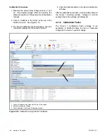
Page 54: ...ace provided 4 Click the Calibrate button in the Device Calibration Window After the calibration procedure view the utility voltage in the Source 1 metering window Voltage L1 L2 and average line to li...

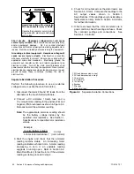
Page 55: ...oes not operate check the K3 relay The individual relays are not replaceable If one or more relays are faulty replace the controller 4 12 2 Controller Fuse F2 The controller board is protected by a 7...

Page 56: ...gs Accidental starting Can cause severe injury or death Disconnect the battery cables before working on the generator set Remove the negative lead first when disconnecting the battery Reconnect the ne...

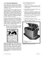
Page 57: ...he receptacle on the generator set 16 Replace the air intake end panel and secure with two screws GM66569 1 Controller screws qty 4 1 1 Figure 4 17 Controller Mounting Screws 1 GM69754 1 P1 2 P3 3 P2...

Page 58: ...the enclosure 4 Be prepared for the system to operate automatically 600 volts and under 19 Press the RUN button on the controller to start the generator set Use a voltmeter to check the output voltage...

Page 59: ...Figure 5 2 Before beginning the test procedures read all safety precautions at the beginning of this manual Many of the test procedures include additional safety precautions Check the condition of the...

Page 60: ...at the brush holder terminals 2 Connect a DC ammeter 10 amp fuse and a 12 volt automotive battery to the positive FP and negative FN brush leads as shown in Figure 5 3 Note and record the ammeter read...

Page 61: ...ment Stator Continuity and Resistance Tests 1 Press the OFF button on the controller to turn off the generator set and remove controller fuse F3 2 Disconnect power to the battery charger 3 Disconnect...

Page 62: ...imate readings Take readings of the rotor and stator at room temperature Note Make sure that all stator leads are disconnected before running the megohmmeter test 9 Use a megohmmeter to determine whet...

Page 63: ...he OFF button on the controller to turn off the generator set and remove controller fuse F3 2 Disconnect power to the battery charger 3 Disconnect the generator set engine starting battery negative le...

Page 64: ...age the controller Weak springs damaged slip rings sticking brushes a loose brush holder or poor brush contact causes arcing The brush holder assemblies are illustrated in Figure 5 9 and Figure 5 10 T...

Page 65: ...4 1 4 1 Brush es 2 Slip rings 3 Brush holder 4 Retainer wire for service only 5 Shim 6 Spring Figure 5 9 Brush Assembly 1 1 Brush es 2 Brush holder 3 Slip rings 4 Shim 5 Spring GM80980 GM80981 Length...

Page 66: ...ust the voltage gain and volts Hz When using the RDC controller keypad the controller will time out and exit the adjustment mode after approximately 1 minute if no buttons are pressed Any unsaved chan...

Page 67: ...15 during the adjustment procedure 1 Connect a digital voltmeter to measure output voltage across L1 or L2 and L0 Set the meter to measure AC volts 2 Start the generator set 3 Follow the controller i...

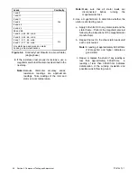
Page 68: ...own in Figure 5 14 by adjusting the engine governor speed 2 Set the voltmeter to measure voltage Adjust the volts Hz until the voltage level measured by the voltmeter begins to drop When set the gener...

Page 69: ...tage Setting Engine Configuration Adjust Setting 1 u U E c 1 3 No Generator Set Running Hold select and up buttons for 5 seconds Enter pass code S AU E Software version number displayed u 1 0 Software...

Page 70: ...owing connections and conditions before adjusting the governor D Power to the governor stepper motor is tied to the K3 run relay If the stepper motor does not operate check the K3 relay See Section 4...

Page 71: ...RES RESL 20RES RESL Figure 5 16 Stepper Motor and Carburetor 5 9 4 Governor System Magnetic Pickup Operation Test If the engine continues to operate erratically after the previous checks test the gove...

Page 72: ...up a If the throttle moves to the fully open throttle position and then steps to and remains in the fully closed position the engine speed input is probably missing The engine starts and then shuts do...

Page 73: ...tic pickup 6 To test controller s governing function disconnect the magnetic pickup leads and open the generator set circuit breaker 7 Manually move the throttle shaft governor stepper motor fully cou...

Page 74: ...speed is unstable hunts or surges check for the cause using the procedure in Section 5 9 3 before proceeding 5 Check stability with the generator set running and with no load applied If the generator...

Page 75: ...performing the following tests If the controller does not operate as described check the controller configuration settings see Section 4 10 1 Also check the controller wiring and connections Overspeed...

Page 76: ...r set shuts down after the third crank rest cycle High Engine Temperature Shutdown Disconnect the harness connector P5 at the engine temperature sensor CTS See Figure 5 22 for the CTS location Connect...

Page 77: ...or the coolant temperature sensor location Press the OFF button on the controller to stop the generator set and allow the generator set to cool Disconnect the CTS and use an ohmmeter to measure the re...

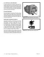
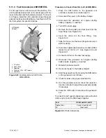
Page 78: ...used by an inadequate fuel supply incorrect adjustments or damaged fuel system components Then use the instructions in this section to check fuel system components 5 11 1 Fuel Solenoid Valve A solenoi...

Page 79: ...id valve and digital spark advance ignition DSAI leads 4 2 3 Enlarged to show detail DSAI Lead Connection Figure 5 27 Fuel System GM80110 1 Regulator 2 Fuel block not shown see Figure 5 32 or LP orifi...

Page 80: ...e is not operating See Figure 5 29 Do not try to adjust the fuel pressure fuel mixture or engine speed using the fuel lockoff Checking the Fuel Pressure Use a gauge or manometer to check the fuel pres...

Page 81: ...t 4 Turn off the fuel supply 5 Remove the hose clamp and fuel hose from the hose fitting See Figure 5 30 6 Insert the orifice into the hose fitting See Figure 5 30 7 Slide the hose onto the hose fitti...

Page 82: ...ck 14RES RESL 6 Remove the hose fitting from the natural gas outlet port in the fuel block See Figure 5 32 7 Remove the plug from the LP port in the fuel block See Figure 5 32 8 Clean the plug with a...

Page 83: ...lways use an oxygen sensor when adjusting the fuel metering valves Observe the following safety precautions while performing the procedure Hot engine and exhaust system Can cause severe injury or deat...

Page 84: ...onnect the generator set engine starting battery negative lead first 16 Allow the generator set exhaust system to cool 17 Disconnect the DVM leads from the oxygen sensor 18 After the sensor has cooled...

Page 85: ...er For rotor and stator resistance and continuity checks see Section 5 3 Stator and Section 5 4 Main Field Rotor Component Ohmmeter Connections Ohmmeter Scale Generator Set State Ohmmeter Readings for...

Page 86: ...4 2 Fuses and Mini Breaker Two fuses and a mini breaker protect the alternator and electrical controls The fuses and breaker are located in the service access area of the RDC DC controller A battery c...

Page 87: ...OFF position 2 Disconnect the power to the battery charger 3 Remove the battery cables negative lead first Reconnect the negative lead last when reconnecting the battery Follow these precautions to pr...

Page 88: ...king notes Remove enclosure Remove the generator set enclosure as described in the following steps See Figure 6 1 1 Open the enclosure roof 2 Press the OFF button on the controller and remove fuse F3...

Page 89: ...Remove 2 screws 1 2 Figure 6 3 Heat Shield original 5 Revised design with thermal cover see Figure 6 4 Remove the thermal cover a Loosen and remove the locknuts from the front and rear hinge brackets...

Page 90: ...sign no latch disassembly is required 7 See Figure 6 6 Remove two nuts on each side total of four nuts 8 Remove one screw near the controller area 9 Pull the right side panel up and off 1 GM72523 1 Di...

Page 91: ...le 13 Disconnect the generator set engine starting battery negative lead first 14 Disconnect output leads or load circuit cables at the field connection terminal block 15 Remove two nuts and lift off...

Page 92: ...nnect the following alternator wiring inside the controller junction box See the wiring diagrams in Section 7 a Disconnect lead 55 from the mini breaker on the controller b Disconnect P2 from the cont...

Page 93: ...rushes are spring loaded Be sure to insert a retaining wire to hold the brushes as described below a Raise the brushes in the brush holder and insert a small piece of wire into the brush holder retain...

Page 94: ...Figure 6 17 4 Stator shell 5 Overbolts qty 4 1 3 2 4 5 Figure 6 16 Alternator Assembly 27 Using a soft faced hammer strike the sides of the end bracket with medium force blows to remove the end brack...

Page 95: ...17 Rotate the rotor and strike it on alternate sides until it can be rocked slightly back and forth Note Do not strike the slip rings c Remove the thrubolt and the rotor Set the rotor assembly aside...

Page 96: ...the actuator and rotor into the crankshaft Do not tighten the thrubolt at this time GM67344 1 1 Rotor thrubolt 2 Hardened washer 3 Fan 3 2 Figure 6 19 Rotor Assembly 3 Install the stator and end brac...

Page 97: ...or shell 5 Overbolts qty 4 1 3 2 4 5 Figure 6 21 End Bracket and Brush Assembly 1 End bracket 2 Alternator 3 Alternator frame vibromount 4 Overbolts 1 2 4 3 6519 Figure 6 22 Generator Set Right Side 4...

Page 98: ...sert spacers between the mounting surface and brush holder to center the brushes on the slip rings See Figure 6 25 or Figure 6 26 See Section 5 6 Brushes for more information d Use the cable tie to se...

Page 99: ...1 Alternator duct 2 Exhaust duct panels 1 2 2 Figure 6 28 Alternator and Exhaust Ducts 10 Reconnect the following alternator wiring inside the controller junction box See the wiring diagrams in Sectio...

Page 100: ...Install the front panel g Install the generator set housing roof 1 Roof 2 Rear panel exhaust end 3 Left side panel 4 Front panel air intake end 5 Right side panel 1 ADV7341 5 4 3 2 Right Side Front ai...

Page 101: ...6 Disassembly Reassembly GM81036 1 Thermal cover 2 Screw 3 Locknut 1 3 3 2 2 REAR HINGE BRACKET VIEW FRONT HINGE BRACKET VIEW SEE FRONT HINGE BRACKET VIEW SEE REAR HINGE BRACKET VIEW Figure 6 32 Ther...

Page 102: ...TP 6735 7 17 102 Section 6 Disassembly Reassembly Notes...

Page 103: ...ield Connection Terminal Block The revised design uses the revised fuel system and the revised field connection terminal block layout shown in Figure 7 2 GM80177 1 Terminal block note location of ATS1...

Page 104: ...TP 6735 7 17 104 Section 7 Wiring Diagrams Figure 7 4 Schematic Diagram ADV 7697 original design...

Page 105: ...TP 6735 7 17 105 Section 7 Wiring Diagrams Figure 7 5 Schematic Diagram ADV 8033 revised design...

Page 106: ...TP 6735 7 17 106 Section 7 Wiring Diagrams Figure 7 6 Point to Point Wiring Diagram GM69754 original design...

Page 107: ...TP 6735 7 17 107 Section 7 Wiring Diagrams Figure 7 7 Point to Point Wiring Diagram GM79591 revised design...

Page 108: ...TP 6735 7 17 108 Section 7 Wiring Diagrams Notes...

Page 109: ...iter s Laboratories CUL Canadian Underwriter s Laboratories cu in cubic inch cw clockwise CWC city water cooled cyl cylinder D A digital to analog DAC digital to analog converter dB decibel dB A decib...

Page 110: ...ersize overspeed OSHA Occupational Safety and Health Administration OV overvoltage oz ounce p pp page pages PC personal computer PCB printed circuit board pF picofarad PF power factor ph phase PHC Phi...

Page 111: ...p of nut 3 Below top of nut Figure 1 Acceptable Bolt Lengths Steps for common hardware application 1 Determine entry hole type round or slotted 2 Determine exit hole type fixed female thread weld nut...

Page 112: ...895 Metric Fasteners Torque Specifications Measured in Nm ft lb Size mm Assembled into Cast Iron or Steel Assembled into Aluminum Grade 5 8 or 8 8 Grade 5 8 Grade 8 8 Grade 10 9 M6 x 1 00 6 2 4 6 9 5...

Page 113: ...al External Tooth Lock Hardness Grades American Standard Grade 2 Grade 5 Grade 8 Grade 8 9 Hex Socket Head Metric Number stamped on hardware 5 8 shown 5 8 Allent head screw is a trademark of Holo Krom...

Page 114: ...4 2 7 16 14 x 1 00 X 6024 8 7 16 14 x 1 25 X 6024 3 7 16 14 x 1 50 X 6024 4 7 16 14 x 2 00 X 6024 11 7 16 14 x 2 75 X 6024 12 7 16 14 x 6 50 X 129 15 1 2 13 x 75 X 129 17 1 2 13 x 1 00 X 129 18 1 2 13...

Page 115: ...00 x 160 M931 24200 60 M24 3 00 x 200 Hex Head Bolts Full Thread M933 04006 60 M4 0 70 x 6 M933 05030 60 M5 0 80 x 30 M933 05035 60 M5 0 80 x 35 M933 05050 60 M5 0 80 x 50 M933 06010 60 M6 1 00 x 10...

Page 116: ...12 1 75 Spiralock M982 12 80 M12 1 75 Elastic Stop M982 14 60 M14 2 00 Elastic Stop M6923 16 80 M16 2 00 Spiralock M982 16 80 M16 2 00 Elastic Stop M934 18 80 M18 2 5 Standard M982 18 60 M18 2 50 Elas...

Page 117: ...99 50 Engine Speed Gain Adjustment Write 0 99 50 Generator Metering Generator Voltage L1 L2 Read V Generator Frequency Read Hz Generator Metering Firmware Version Read Genset Info Genset Model Number...

Page 118: ...Warning Limit Write 110 135 125 Genset Battery Low Cranking Voltage Warning Delay Read s 6 Genset Battery Low Cranking Voltage Warning Limit Read 60 Engine Protection Engine High Oil Temperature Shut...

Page 119: ...ce 2 Low Voltage Pickup Write 85 100 90 Source 2 Low Voltage Dropout Write 75 98 90 ATS Exercise Exercise Interval Write Weekly 5 2 Weeks 6 Weekly 5 Exercise Run Duration Write min 10 30 20 Exercise M...

Page 120: ...TP 6735 7 17 120 Notes...

Page 121: ...TP 6735 7 17 121 Notes...

Page 122: ...TP 6735 7 17 122 Notes...

Page 123: ......

Page 124: ...Pacific Headquarters 7 Jurong Pier Road Singapore 619159 Phone 65 6264 6422 Fax 65 6264 6455 For the nearest KOHLER authorized installation service and sales dealer in the US and Canada Call 1 800 544...

Reviews: