TP-6735 7/17
96
Section 6 Disassembly/Reassembly
6.3 Reassembly
1. 14RES/RESL only:
Reinstall the generator
adapter onto the engine, if necessary.
a. Attach the generator adapter to the engine
using four 7/16-14 x 1.0 in. hex cap bolts and
washers. See Figure 6-18.
b. Torque the bolts to 40 Nm (28 ft. lb.).
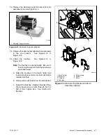
2. Install the rotor. See Figure 6-19.
a. Clean the crankshaft stub and mating surface
on the fan hub. Do not use antiseize compound
when reassembling the rotor.
b. Install the rotor onto the engine crankshaft.
c. Thread the thrubolt with hardened washer
through the actuator and rotor into the
crankshaft. Do not tighten the thrubolt at this
time.
GM67344
1
1. Rotor thrubolt
2. Hardened washer
3. Fan
3
2
Figure 6-19
Rotor Assembly
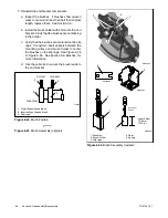
3. Install the stator and end bracket.
a. Re-attach the alternator support bracket to the
alternator shell. The hole in the bracket must
face the engine. See Figure 6-20.
1
GM67344
1. Alternator support bracket
Figure 6-20
Alternator Support Bracket
b. Align the stator so that the alternator support
bracket is at the bottom. Install the stator
assembly around the rotor.
c. Align the alignment mark on the top of the stator
with the center of the slot in the generator
adapter.
d. Route the leads connected to the alternator
end bracket through the opening in the base of
the alternator frame.
Summary of Contents for 14RES
Page 2: ......
Page 6: ...TP 6735 7 17 6...
Page 16: ...TP 6735 7 17 16 Section 1 Specifications Notes...
Page 102: ...TP 6735 7 17 102 Section 6 Disassembly Reassembly Notes...
Page 108: ...TP 6735 7 17 108 Section 7 Wiring Diagrams Notes...
Page 120: ...TP 6735 7 17 120 Notes...
Page 121: ...TP 6735 7 17 121 Notes...
Page 122: ...TP 6735 7 17 122 Notes...
Page 123: ......


