TP-6198 3/15
40 Section 4 Controller
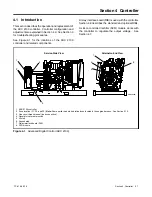
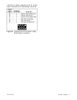
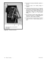
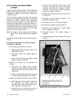
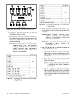
1. Engine wiring harness connector plug (P1)
2. J15 connector
3. J16 connector
tp6196
1
2
3
Figure 4-11
Controller Connections
10. Reconnect the engine starting battery, negative (--)
lead last.
11. Reconnect power to the battery charger, if
equipped.
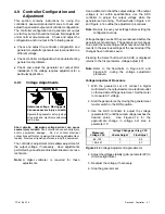
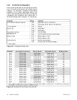
12. Follow the instructions in Section 4.9 to change the
new controller’s configuration settings to match the
generator set system voltage and frequency, unit
configuration, engine type, engine data input
types, battery voltage, and communications
settings.
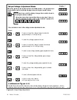
13. Use a voltmeter to check the output voltage. Follow
instructions in Section 5.7.2, Voltage Adjustment,
to adjust the output voltage and stability.
14. Place the generator set master switch in the AUTO
position if an ATS or remote start/stop switch is
used.
Summary of Contents for 15/30RES
Page 2: ......
Page 18: ...TP 6198 3 15 18 Section 1 Specifications Notes ...
Page 62: ...TP 6198 3 15 62 Section 5 Component Testing and Adjustment Notes ...
Page 71: ......


