TT-1601 5/16
6
GM86016E--B
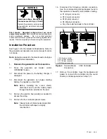
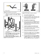
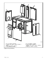
1. Clamp (X-672-32)
1
Figure 10
Fuel Return Line Connections
4.6 Bleed the air from the fuel system according to the
procedure provided in the engine operation
manual.
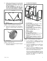
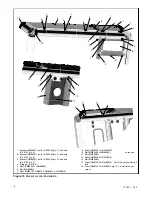
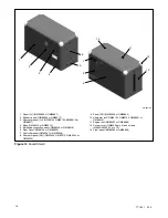
GM86016-
1. Hose (GM92558) and hose clamp (X-426-5). Attach hose to
air cleaner inlet.
2. Flex fuel line (GM86395). Attach to fuel inlet on engine.
3. Flex fuel line (GM86395), clamp (X-672-32) and straight
union (X-695-2). Attach to fuel return on engine.
4. Hose (X-6014-66) and hose clamps (X-426-19 qty. 2).
Attach to seawater inlet on engine.
5. Bulkhead connection panel (GM86346 or GM88918).
1
2
3
4
5
Figure 11
Internal Connections
GM86016B-A
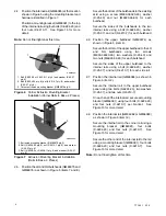
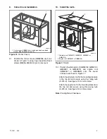
1. Fuel supply connection
1
1
Figure 12
Fuel Supply Connection Locations
5.
Connect the seawater hose.
5.1 Connect the seawater hose (X-6014-66) to the
seawater inlet on the engine and secure with a
hose clamp (X-426-19). See Figure 11.
6.
Connect the air cleaner hose.
6.1 Position the air cleaner hose (GM92558) through
the upper bulkhead as shown in Figure 11 (item 1)
and secure the hose to the air cleaner inlet using a
hose clamp (X-426-5).
7.
Install the bulkhead connection panel.
7.1 Connect the fuel-inlet line to the fuel-inlet opening
on the bulkhead connection panel.
7.2 Connect the fuel-return line to the fuel-return
opening on the bulkhead connection panel.
7.3 Connect the seawater hose to the seawater
connection on the bulkhead connection panel and
secure with a hose clamp (X-426-19).
7.4 Secure the bulkhead connection panel (GM86346
or GM88918) to the corner rails (GM86079) using
brackets (GM86091 qty. 2), bolts (X-6224-20
qty. 4) and nuts (X-6210-7 qty. 4). See Figure 13.
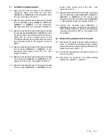
Summary of Contents for 40EFOZDJ
Page 15: ...TT 1601 5 16 15 Notes ...


