background image


TP-6694 

9/20 

167 

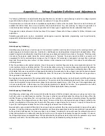
Frequency Setpoint or Cut-In Point 

The point at which the underfrequency unloading begins to take effect is adjustable, allowing the system to be tailored for each 
application.  Because  the  characteristics  of  the  engine  have  the  largest  effect  on  the  system’s  performance,  the  engine’s 
response should determine the unloading point. The unloading setpoint is the frequency below which the excitation control will 
reduce the voltage so that the engine may begin to recover. 

The cut-in point, or frequency setpoint, should be set 0.5- 3.0 Hz lower than the normal steady-state band of operation. If the 
engine normally operates within a very narrow range of speeds close to the nominal, a setpoint of 0.5 to 1.0 Hz below nominal 
should be suitable. If the engine normally operates over a wide range of speeds, the setpoint may need to be 2.0- 3.0 Hz from 
the nominal. The underfrequency unloading function can be eliminated by setting the cut-in point below the minimum expected 
operating frequency. 

Example 

A 90 kW load is applied to a 100 kW, 60 Hz generator set driven by a turbocharged diesel engine with an electronic control 
module (ECM). The speed drops 10% and takes 20 seconds to recover to at least 59.5 Hz. The voltage, meanwhile, drops from 
480  to  460  and  recovers  to  480  within  15  seconds.  Therefore,  some  underfrequency  unloading  should  be  provided.  A  good 
starting point would be a frequency setpoint or cut-in of 59 Hz. A slope of 15 volts per-cycle-per-second is appropriate as well. 
If after these adjustments the speed recovers very quickly, in about 5 seconds, but the voltage drops below 440 volts, the slope 
should be reduced to 12 volts per cycle. More adjusting may be required to get the most desirable compromise between speed 
and voltage. 

Three-Phase Sensing 

Three-phase sensing describes how the excitation control or voltage regulator determines the condition of the alternator output 
voltage. Early types of regulators sensed the voltage on just one phase of the alternator. Single-phase sensing is not uncommon 
today  as  most  alternators  are  designed  to  produce  balanced,  equal  voltage  on  all  three  phases.  If  the  loads  applied  to  the 
generator set including no load are equal and balanced, the output voltage on each phase will be nearly equal. 

However, in some applications, individual phases may have unequal or unbalanced loads. In these cases, the output voltages 
will not be equal on each phase. In general, the phase with the greatest load will have the lowest voltage while the phase with 
the least load will have the highest voltage. This is true regardless of the type of sensing used in the regulator system. A single-
phase sensing excitation controller will keep the voltage of the sensed phase at the voltage adjustment value. A three-phase 
sensing system will average the three phases and hold the average to the adjustment setting. The average is the sum of the 
voltages of three phases divided by 3. 

As stated above, three-phase sensing does not eliminate the unequal voltage phenomenon. Three-phase sensing balances the 
inequality of voltage between the phases to the desired value. In other words, if a system with unbalanced loads uses a single-
phase control feedback, the voltage on the sensed phase would be at the setpoint while the other two phases would vary by 
their proportional loads. For example, if the sensed phase had rated load while the two other phases were only loaded at half 
the rated value, those two phases would have higher-than-rated voltage which may be undesirable. If a three-phase sensing 
feedback were utilized, the phase with rated load would be regulated to a voltage slightly below the rated voltage while the other 
two phases would be slightly above the rated voltage (but lower than in the previous case). The sum of the three, divided by  3, 
would be equal to the regulation setpoint. 

In a single-phase system, line-to-line voltage is held equal to the line-to-line voltage adjust setting. In a three-phase system, the 
average of the three line-to-line voltage is regulated to the voltage adjust setting. In some cases, it may be desirable to keep 
one phase at a particular value. Modify the voltage adjust setting higher or lower accordingly for any unique requirements for 
the particular application. 


Summary of Contents for APM402

Page 1: ...Models 10 1000 kW Controller APM402 Decision Maker 3000 Industrial Generator Set TP 6694 9 20m Operation ...

Page 2: ...ts so that the numbers are readily available for future reference Record field installed kit numbers after installing the kits Generator Set Identification Numbers Record the product identification numbers from the engine nameplate s Model Designation _________________________________________________________ Specification Number _______________________________________________________ Serial Number...

Page 3: ...g Generator Set 44 2 3 Operations in Cold Weather Climates 44 2 4 Controller Operation 44 2 4 1 Starting 45 2 4 2 Stopping User Stopping and Fault Shutdown 46 2 4 3 Emergency Stop Switch Resetting 46 2 4 4 System Status Lamps 46 2 4 5 System Fault Warning Lamp with Digital Displays 46 2 4 6 System Fault Shutdown Lamp with Digital Displays 49 2 4 7 Status and Notice Digital Displays 52 2 4 8 Contro...

Page 4: ... 101 3 8 Air Cleaner Restrictor Indicator if equipped 101 3 9 Cooling System 102 3 9 1 Coolant Level Check 102 3 9 2 Cooling System Component Inspection 102 3 9 3 Procedure to Drain Cooling System 103 3 9 4 Procedure to Flush and Clean Cooling System 103 3 9 5 Procedure to Refill Cooling System 103 3 10 Battery 104 3 10 1 Clean the Battery 106 3 10 2 Electrolyte Level Inspection 106 3 10 3 Specifi...

Page 5: ...Manual Speed Adjust Engine RPM Menu 141 6 1 10 Prime Power Switch Kit 141 6 1 11 Remote Emergency Stop Kit 142 6 1 12 Remote emergency stop kit 142 6 1 13 Lockable Emergency Stop Switch 142 6 1 14 Remote Reset Feature 144 6 1 15 Remote Serial Annunciator 145 6 1 16 Run Relay Kit 147 6 1 17 Shunt Trip Line Circuit Breaker 148 6 2 Accessory Connections 149 Appendix A Abbreviations 155 Appendix B Pro...

Page 6: ...6 TP 6694 9 20 ...

Page 7: ...nt places alert the operator or service technician to potential hazards and explain how to act safely The decals are shown throughout this publication to improve operator recognition Replace missing or damaged decals Accidental Starting WARNING Accidental starting Can cause severe injury or death Disconnect the battery cables before working on the generator set Remove the negative lead first when ...

Page 8: ...er connections while the battery is charging Always turn the battery charger off before disconnecting the battery connections Ventilate the compartments containing batteries to prevent accumulation of explosive gases Battery short circuits Explosion can cause severe injury or death Short circuits can cause bodily injury and or equipment damage Disconnect the battery before generator set installati...

Page 9: ...ury or death Use extreme care when handling storing and using fuels The fuel system Explosive fuel vapors can cause severe injury or death Vaporized fuels are highly explosive Use extreme care when handling and storing fuels Store fuels in a well ventilated area away from spark producing equipment and out of the reach of children Never add fuel to the tank while the engine is running because spill...

Page 10: ...5 dBA can cause permanent hearing loss Wear hearing protection when near an operating generator set Hazardous Voltage Moving Parts DANGER Hazardous voltage Will cause severe injury or death Disconnect all power sources before opening the enclosure DANGER Hazardous voltage Moving parts Will cause severe injury or death Operate the generator set only when all guards and electrical enclosures are in ...

Page 11: ...nstallations to prevent the connection of standby and other sources of power Electrical backfeed into a utility electrical system can cause severe injury or death to utility personnel working on power lines Testing live electrical circuits Hazardous voltage or current will cause severe injury or death Have trained and qualified personnel take diagnostic measurements of live circuits Use adequately...

Page 12: ...r death Do not touch hot engine parts The engine and exhaust system components become extremely hot during operation Notice NOTICE This generator set has been rewired from its nameplate voltage to 246242 NOTICE Voltage reconnection Affix a notice to the generator set after reconnecting the set to a voltage different from the voltage on the nameplate Order voltage reconnection decal 246242 from an ...

Page 13: ... this manual Keep this manual with the equipment for future reference The equipment service requirements are very important to safe and efficient operation Inspect the parts often and perform required service at the prescribed intervals Maintenance work must be performed by appropriately skilled and suitably trained maintenance personnel familiar with generator set operation and service Abbreviati...

Page 14: ...bus Communications Protocol Operation Manual TP 6113 SiteTech Software Operation Manual TP 6701 Remote Serial Annunciator RSA III TT 1625 Remote Serial Annunciator RSA II TT 1485 Converters Connections and Controller Setup for Network Communication TT 1405 Figure 1 Related Literature Several engine manufacturers provide engines with electronic controls These electronic controls indicate engine fau...

Page 15: ...ast Africa EMEA Kohler EMEA Headquarters Netherlands B V Kristallaan 1 4761 ZC Zevenbergen The Netherlands Phone 31 168 331630 Fax 31 168 331631 Asia Pacific Kohler Asia Pacific Headquarters Singapore Republic of Singapore Phone 65 6264 6422 Fax 65 6264 6455 China North China Regional Office Beijing Phone 86 10 6518 7950 86 10 6518 7951 86 10 6518 7952 Fax 86 10 6518 7955 East China Regional Offic...

Page 16: ...16 TP 6694 9 20 ...

Page 17: ...ler features accessories and menu displays depend upon the engine electronic control module ECM setup and features Controller features apply to generator set models with ECM and non ECM engines unless otherwise noted Note Press the pushbutton rotary selector dial to turn on the controller lights and display The lights and display turn off 60 minutes after the last entry when in the AUTO mode Note ...

Page 18: ... two seconds to test the controller indicator lamps alarm horn and digital display Manual Speed Adjust Engine RPM The control allows varying the engine speed for applications using closed transition ATS The user can set the nominal running frequency slightly above or below the utility frequency to ensure that synchronization occurs Additional information is shown in the section titled GenSet Syste...

Page 19: ...Yellow lamp illuminates indicating the alarm horn was silenced System Fault Lamp Yellow lamp illuminates indicating a warning condition or red lamp illuminates indicating a shutdown condition See System Warning Fault Lamp and System Shutdown Fault Lamp following for system fault conditions System Warning Fault Lamp Yellow lamp identifies an existing fault condition that does not shut down the gene...

Page 20: ... the controller see the section titled Controller Resetting procedure See the section titled System Fault Shutdown Lamp with Digital Displays for definitions of the items listed The following conditions cause a system shutdown AC sensing loss Alternator protection Auxiliary input analog or digital Common fault ECM address conflict ECM communications loss ECM diagnostics multiple engine inputs ECM ...

Page 21: ...r Displays from the Engine ECM The 12 character 2 line backlit heated display provides generator set and engine data system status and fault information See the figure titled Controller with Digital Display and Pushbutton Rotary Selector Dial The digital display shows abbreviations in some instances Refer to the section titled Status Event and Fault Specifications for the abbreviations and their f...

Page 22: ... for three phase configurations or the current value for L1 L2 with single phase configurations Average kW displays For three phase configurations the average line to line kilowatts of L1 L2 and L3 is displayed Single phase configurations show the L1 L2 kilowatts Coolant Temperature displays for the engine coolant temperature Oil Pressure displays the engine oil pressure Fuel Level displays the fu...

Page 23: ...tion providing the means to reset the configuration values is available in this menu The calibration values are reviewable at all times and provide the calibration of the voltage and current sensing logic Changing the system voltage or replacing the circuit board requires a calibration adjustment To enable calibration start the generator set and select the Volts L1 L2 display Then push and hold th...

Page 24: ... to improve digital display clarity Alarm Horn Silence displays the programmer selected alarm silence method as Always or Auto Only using SiteTech software The Always selection allows the alarm to be silenced in any of the OFF RESET AUTO RUN modes The Auto Only selection allows silencing of the alarm only while in the Auto mode Note Press the Alarm Silence Lamp Test button to silence the alarm hor...

Page 25: ...en the Enter volt reg is shown the display returns to the Voltage Regulator main menu and entry to the Voltage Regulator menu is denied If the unit is running and Yes is entered when the Enter volt reg is shown the display will show the value The user can change the value at this time At the end of the Voltage Regulator menu Exit voltage reg is shown press the pushbutton rotary selector dial to ex...

Page 26: ...digital output on the controller is used to drive the optional I O Module board and becomes factory reserved and no longer available as programmer selectable The displays for digital outputs appear as shown in the following list with Values as True or False Items shown in the digital display as True are active DOut A1 digital output A1 standard DOut B1 digital output B1 with I O module board DOut ...

Page 27: ...e volt select menu requires initial activation by SiteTech software In SiteTech software select True to activate the volt select menu Note The generator set output leads require voltage reconnection if the generator set does not have a voltage selector switch installed With the generator set stopped go to the Volt Select menu Then push and hold the pushbutton rotary selector dial until the voltage...

Page 28: ...xxxx Shutdwn X X ECM faults address conflict ECM Addr Err Shutdwn X X ECM faults model mismatch ECM Mismatch Shutdwn X X Engine over speed Eng Speed High Shutdwn X X Engine start aid active Starting Aid Notice N X Engine under speed Eng Speed Low Shutdwn X X Fuel tank leak Fuel Leak Warning X X Fuel tank leak Fuel Leak Shutdwn X X High battery voltage Battery High Warning X X High coolant engine t...

Page 29: ...lt X Chicago code active Chicago Code Active N X Common fault includes Common Fault Shutdwn X N X Common warning fault Common Warng X N X Default parameters loaded Default Pars Warning X X Emergency stop Emerg Stop Shutdwn X X Enclosure temperature high shutdown Enclsr Temp High Shutdwn X X Engine cooldown delay active Eng Cooldown Notice N X Engine started Engine Start Status S X Engine stopped E...

Page 30: ...ch light Mini USB connector for PC setup using SiteTech software See Figure 4 Digital Display Circuit Board Connectors Figure 4 for the circuit board connections Circuit Board Connections P9 Connector the 24 pin connector attaches directly to the main logic circuit board P10 Connector mini USB for PC upgrades located on the front panel using SiteTech software P11 Connector is a 20 pin connector no...

Page 31: ...it and circuit protection fuses See Figure 5 and Figure 6 for the circuit board connections See the section titled Accessories for more information Figure 5 Main Circuit Board and Emergency Stop Switch Circuit Board Connections P1 24 Pin Connector for engine generator wiring harness 4 Push on Connectors for V7 V8 V9 V0 for generator set output voltage connection Main logic circuit board Remote eme...

Page 32: ...l Block for E stop remote start contacts and aux input connections 1 2 7 Terminal Jumper A circuit board P30 jumper is set based on alternator type Wound Field 300 kW and larger or Fast Response less than 350 kW The jumper is factory set and needs no further adjustment See the figure titled Main Circuit Board Connectors for location of the P30 jumper Modbus is a registered trademark of Schneider E...

Page 33: ...are located inside the generator set control box See Figure 8 1 5 Amp V7 fuse protects L1 sensing input to interconnection circuit board 1 5 Amp V8 fuse protects L2 sensing input to interconnection circuit board 1 5 Amp V9 fuse protects L3 sensing input to interconnection circuit board DC Circuit Fuses are located on the controller circuit board See Figure 9 1 Amp F1 auto resettable fuse protects ...

Page 34: ... operation manual for details Inhibit Time Delay The inhibit time delay is the time period following crank disconnect during which the generator set stabilizes and the controller does not detect a fault or status event Select the desired inhibit time delay from 0 to 60 seconds Time Delay Shutdown or Warning The time delay follows the inhibit time delay The time delay is the time period between whe...

Page 35: ...A 105 120 115 Engine start aid active Starting Aid Notice Engine under speed Eng Speed Low Shutdwn On S S A 75 95 85 Fuel tank leak Fuel Leak Warning On W Fuel tank leak Fuel Leak Shutdwn On S High battery voltage Battery High Warning On W S A 110 135 125 Fixed 10 High coolant temperature Coolnt Temp High Warning On W 0 10 0 30 inhibit 0 5 FAA 0 inhibit High coolant temperature Coolnt Temp High Sh...

Page 36: ...ence Mode S A 0 1 1 Aux inputs 0 5 VDC 1 analog Aux Input Warning On W 0 100 100 0 10 0 Aux inputs 0 5 VDC 1 analog Aux Input Shutdwn On S 0 100 100 0 10 0 Auxiliary inputs up to 3 digital 2 additional digital inputs available with I O module option Aux Input Warning On W 0 10 0 30 inhibit 0 0 inhibit Auxiliary inputs up to 3 digital 2 additional digital inputs available with I O module option Aux...

Page 37: ...output optional module board communication loss OB1 Com Loss On W Internal failure Intern Error Shutdwn On S Measurement Units 0 English 1 Metric Measurement Display DS A 0 1 1 Metering communication loss MeterComm Loss Shutdwn On S NFPA 110 alarm active NFPA Alarm Notice Not in auto master control buttons Not In Auto Warning On W Prime power application 0 Standby 1 Prime Power Type DS A 0 1 0 Rem...

Page 38: ...guration 0 Single phase 1 Single phase dogleg 2 three phase wye 3 three phase delta SystemPhase DS S 0 3 2 Voltage regulator average voltage adjustment VR Volt Adj DS R 108 600 208 Voltage regulator communication loss RegCommLoss Shutdwn On S SiteTech Read Write Display Only Charger Absorption Current Termination Target A S A 1 5 2 Charger Automatic Equalize Enable Note Equalize is only available ...

Page 39: ...rify that the battery topology is set correctly for the battery type that is used Incorrect charger output system voltage may cause irreversible damage to the battery and abnormal out gassing S A Default FLA VRLA AGM Gel NiCad Default Charger System Battery Voltage Note Verify that the system voltage is set correctly for the battery type that is used Incorrect charger output system voltage may cau...

Page 40: ...0 60 60 Engine no of cyclic crank cycles S S 1 6 3 Engine restart delay S A 1 10 10 Engine start aid delay S A 0 10 0 Engine start delay S A 0 300 0 Equalize Current Limit A Note Equalize is only available with FLA VRLA topology selected S A 1 5 Forced Charge Cycle Reset S A Active Inactive Inactive Output Enable Fixed Active System battery voltage S S 12 24 12 Voltage regulator gain S R 1 255 128...

Page 41: ... voltage adjust setpoint can be changed to accommodate an important phase in an unbalanced system Underfrequency Unload Frequency Setpoint This adjustment affects the voltage droop volts per Hz when load is applied and underfrequency occurs The underfrequency unload setting defines the setpoint where underfrequency starts Any frequency below the setpoint causes the voltage to drop thus reducing th...

Page 42: ...42 TP 6694 9 20 ...

Page 43: ...tor to purge the air from the system before energizing the block heater Drive Belts Check the belt condition and tension of the radiator fan water pump and battery charging alternator belt s according to the drive belt system maintenance information Exhaust System Check for exhaust leaks and blockages Check the silencer and piping condition and check for tight exhaust system connections Inspect th...

Page 44: ...c sheet for temperature recommendations in available options A battery heater is generally recommended for most units when operated below 0 C 32 F Refer to the respective spec sheet for model availability An alternator strip heater is available for most generator sets providing a heat source to prevent moisture and frost buildup The crankcase ventilation CCV heater kit provides a controlled heatin...

Page 45: ...ructions on how to install the optional prime power switch kit The prime power switch kit prevents engine starting battery drain when the generator set is shut down and no external battery charging is available Move the prime power switch located on the junction box to the CONTROLLER ON position before attempting to start the generator set When the prime power mode is off all controller functions ...

Page 46: ...ed Controller Resetting procedure to restart the generator set following a fault shutdown 1 Investigate and correct the cause of the emergency stop 2 Reset the optional remote emergency stop switch by replacing the glass piece when equipped Additional glass rods are available as a service part Reset the controller emergency stop switch by pulling the switch dial outward 3 Press the generator set m...

Page 47: ...there is a CAN address communication error The battery charger has the same CAN address as another generator set component To correct a CAN address error verify the address identification in the harness and power cycle the controller Local display shows BatIdErr Battery Charger Parameter Mismatch The warning lamp on controller illuminates yellow and the alarm horn sounds when the battery charger m...

Page 48: ... 12for low battery voltage specifications Engine Electrical System Voltage Low Battery Voltage Range Low Battery Voltage Default Setting 12 9 6 12 6 12 24 19 2 25 2 24 Figure 12 Low Battery Voltage Specs The low battery voltage feature monitors the battery and battery charging system in the generator set operating and off modes The controller logic inhibits the low battery voltage warning during t...

Page 49: ...nit shuts down when the controller is signaled by a common fault Use SiteTech software to activate the common fault shutdown The local display shows Common Fault Shutdwn The common fault comprises the following shutdowns under a single alert Emergency stop Engine over speed High coolant temperature Low oil pressure Overcrank ECM Address Conflict The fault lamp illuminates red the alarm horn sounds...

Page 50: ...luminates red and the alarm horn sounds when the unit shuts down without receiving a signal from the controller to do so On diesel fueled units this condition includes fuel pump failure loss of fuel prime and or an empty fuel tank On gaseous fueled units this condition includes loss of fuel pressure and or an empty fuel tank The local display shows Loss of Fuel Low Coolant Level The fault lamp ill...

Page 51: ...ing faster than 2 second shutdown Overvoltage Setting Range Time Delay Overvoltage Default Setting 105 135 of nominal 2 10 sec 120 at 2 sec Figure 14 Overvoltage Specs Run Relay Overload The fault lamp illuminates red the alarm horn sounds and the unit shuts down when the controller smart switch that operates generator set wire number 70 Run is overloaded The local display shows Run Relay Overload...

Page 52: ...S Supplying Load This notice message indicates when the generator set supplies more than 1 of the rated standby output current The local display shows Emerg Pwr On Notice Engine Cooldown Delay Active This notice message indicates that the delay for engine cooldown is active where the generator set will continue to run after the OFF RESET button is pressed The unit will continue to run until the ti...

Page 53: ...e NFPA 110 fault signals the controller The local display shows the respective fault message The NFPA 110 faults include Battery charger fault EPS supplying load High battery voltage High coolant temperature shutdown High coolant temperature warning High engine speed Low battery voltage Low coolant level Low coolant temperature warning Low fuel level or pressure Low oil pressure shutdown Low oil p...

Page 54: ...ct the cause of the fault shutdown or warning See the Safety Precautions and Instructions section of this manual before proceeding 3 Start the generator set by pressing the generator set master control OFF RESET button and then press the RUN button When equipped the remote annunciator alarm horn sounds Press the ALARM SILENCE LAMP TEST button to stop the alarm horn The lamp turns off 4 Test operat...

Page 55: ...ngine ECM power up procedure Procedure for Checking the Firmware Version 1 Confirm that a fully charged battery is connected to the generator set 2 Press the generator set controller OFF RESET key 3 Momentarily press the selector dial to activate the digital display if dark 4 Rotate the selector dial counterclockwise to navigate through the main menus to the Overview Menu as shown in Figure 17 Fig...

Page 56: ...le menus Procedure for Powering Up the Engine ECM using SiteTech for Decision Maker 3000 controllers with Firmware Versions Before 3 10 Connect a PC with SiteTech software to the generator set controller Refer to the SiteTech Software Operation Manual TP 6701 as needed Follow the instructions shown in Figure 22 Figure 22 SiteTech Software Display Screen ECM Powered ECM powered Push to Stop Click d...

Page 57: ...esel powered models and optional fuel tank sender Fuel Pressure engine dependent Battery DC Voltage Engine Run Time Battery Charger Volts and Amps CHG1 and CHG2 with charger GM87448 only Software Version Total Power kVA shown as actual output values Total Power kW shown as actual output values Rated Power Volts L1 L2 Volts L2 L3 Volts L3 L1 Volts L1 N Volts L2 N Volts L3 N Current L1 Current L2 Cu...

Page 58: ...with I O Board Volt Select o 120 240 V 1 Ph o 120 208 V 3 Ph o 139 240 V 3 Ph o 277 480 V 3 Ph o 120 240 V 3 Ph Voltage Regulator Voltage Adjust Reset Voltage Regulator Settings o Reset Voltage Regulator Digital Outputs Menu DOut A1 DOut B1 with I O Board DOut B2 with I O Board DOut B3 with I O Board DOut B4 with I O Board DOut B5 with I O Board Battery Charger 1 Menu Output Volts Output Amps Char...

Page 59: ...tions Communicate between a PC and the generator set controller logic using USB communication protocol The PC connections require optional SiteTech software Contact your authorized distributor dealer for assistance Local Single Connection A PC connects to the USB port of the generator set controller using a mini USB connector See Figure 23 Figure 23 Local Single Connection Remote Single Connection...

Page 60: ...ar applications Figure 25 Modbus Connections 2 7 Reviewing Menu Displays Use this section to review a summary of the generator set controller data See Figure 26 or Figure 27 for which menus provide data monitoring data adjustments or require SiteTech software to make data adjustments Use the pushbutton rotary selector dial to navigate to the respective menus Menu Name Controller Viewable Controlle...

Page 61: ...n Time X GenSet System X X X Voltage Regulation X X X Digital Inputs X X Digital Outputs X X Analog Inputs X X Battery Charger 1 X X Battery Charger 2 X X Event Log X Volt Select X X X Requires initial activation using SiteTech Figure 28 Menu Displays for Viewing and Adjusting DEC3000 Firmware Version 3 0 25 to 4 8 4 See the section titled Specifications and Features to review set point ranges and...

Page 62: ...arm horn sounds when the controller detects that the default parameter settings were loaded using SiteTech software The local display shows Default Pars Warning ECM Address Conflict The fault lamp illuminates red the alarm horn sounds and the unit shuts down when the controller detects an error with the ECM address The local display shows ECMAddr Err Shutdwn ECM Model Mismatch The fault lamp illum...

Page 63: ...u item Overview Turn the rotary dial to select the desired fixed view Note Some displays are engine dependent refer to the Appendix titled Controller Displays from the Engine ECM Overview Auto Scrolling Display Overview hr Active Shutdowns if present Active Warnings if present GenSet State Avg V L L V Frequency Hz Current A Average kW kW Coolnt Temp F Oil Pressure PSI Fuel Level Fuel Pressure PSI ...

Page 64: ...e menu overview The phase designation does not appear in the controller menu displays Some displays will show 0 values when single phase connections are shown Note For Decision Maker 3000 controllers with firmware versions before 3 0 25 see the section titled GenSet Calibration for generator calibration Display also provides access to the calibration factors for metering volts and amps Changing th...

Page 65: ... select Reset Calib Yes to reset all voltage and current values The Reset Calib display will only show if calibration is enabled When calibrating voltage the metered value and the number being entered as the calibrated value must be within 10 of the system operating voltage When calibrating current the metered value must be at least 25 of the rated current on units smaller than 100 kW and at least...

Page 66: ... VA Total Power W Rated Power Volts L1 L2 V Volts L2 L3 V Volts L3 L1 V Volts L1 N A Volts L2 N A Volts L3 N A Current L1 A Current L2 A Frequency Hz Reset Calibration Reset Calib No Select this Display to Enable or Disable Calibration CURRENT L3 A Reset calib yes OR ...

Page 67: ...play is user adjustable to help improve digital display visibility in dimly lit rooms or in direct sunlight Note The contrast feature is a controller hardware change and may not be available on older units even if the firmware is updated The alarm horn silence display is programmer selectable to Always or Auto Only using SiteTech software The Always selection allows the alarm to be silenced in any...

Page 68: ...of them The local display Reset all calib No or Yes Select No to make no changes and exit GenSet Calibration Select Yes to reset all of the values When calibrating voltage the metered value and the number being entered as the calibrated value must be within 10 of the system operating voltage When calibrating current the metered value must be at least 25 of the rated current on units smaller than 1...

Page 69: ...lib Yes Volts L1 L2 V Volts L2 L3 V Volts L3 L1 V Volts L1 N A Volts L2 N A Volts L3 N A Current L1 A Current L2 A Current L3 A Reset calibration Reset calibration Reset calibration Exit Calibration User Selectable GenSet Calibration OR Reset all Calib No Reset all Calib Yes OR ...

Page 70: ...ech software The voltage regulator value is reviewable at all times and provides the ability to fine adjust voltage Changing the system voltage or replacing the circuit board typically requires a voltage adjustment To enable calibration start the generator set and select the VR Volt Adj display Then push and hold the pushbutton rotary selector dial until the Editing Enabled popup appears Editing o...

Page 71: ...software The following terms and descriptions are part of the setup procedure Note DIn A3 digital input is factory reserved for Enclosure Temperature High Shutdown on select Telecom units Enabled This menu indicates whether or not the input is enabled If the input is not enabled the controller will ignore this input signal Inhibit Time Delay The inhibit time delay is the time period following cran...

Page 72: ...lse Items shown in the display as True are active DOut A1 digital output A1 standard DOut B1 digital output B1 with I O module board DOut B2 digital output B2 with I O module board DOut B3 digital output B3 with I O module board DOut B4 digital output B4 with I O module board DOut B5 digital output B5 with I O module board Use SiteTech software for digital output selection and setup adjustments Ea...

Page 73: ... Digital Outputs DOut A1 DOut A1 Value True or False DOut B1 DOut B1 Value True or False DOut B2 DOut B2 Value True or False DOut B3 DOut B3 Value True or False DOut B4 DOut B4 Value True or False DOut B5 DOut B5 Value True or False ...

Page 74: ...king Voltage X ECM Comm Loss X Emergency Stop X Engine Coolant Level X Engine Coolant Temperature X X X X X Engine Cooldown Active X Engine Fuel Level X X X X Engine Oil Level X X Engine Oil Pressure X X X Engine Speed X X Engine Start Aid Active X Engine Start Delay Active X EPS Supplying Load X Fuel Pressure X Fuel Tank Leak X X Generator Frequency Average X X Generator Running X Generator True ...

Page 75: ...oftware AIn B1 analog input B1 with I O module board AIn B2 analog input B2 with I O module board All analog input selection and setup adjustments are done using SiteTech software The following terms and descriptions are part of the setup procedure Enabled This menu indicates whether or not the input is enabled If the input is not enabled the controller will ignore this input signal Inhibit Time D...

Page 76: ...e available on Decision Maker 3000 Controllers with controller firmware version 4 8 4 and higher and on APM402 controllers Battery Charger 1 and 2 menus provide battery charger information and metering Use this menu to view the charger output metering and charger states Note Incorrect charger output system voltage may cause irreversible damage to the battery and abnormal out gassing Ensure that th...

Page 77: ...age on the nameplate Order voltage reconnection decal 246242 from an authorized service distributor dealer Note The volt select menu requires initial activation by SiteTech software In SiteTech software select True to activate the volt select menu Note The generator set output leads require voltage reconnection if the generator set does not have a voltage selector switch installed With the generat...

Page 78: ...78 TP 6694 9 20 ...

Page 79: ... it cools Servicing the exhaust system Hot parts can cause severe injury or death Do not touch hot engine parts The engine and exhaust system components become extremely hot during operation DANGER Hazardous voltage Moving parts Will cause severe injury or death Operate the generator set only when all guards and electrical enclosures are in place Servicing the generator set when it is operating Ex...

Page 80: ...e protection level Six Months Air ducts louvers X X Yearly Coolant Yearly Heat exchanger X Yearly Louver motors and controls X X X Yearly Radiator exterior X Yearly Water supply to heat exchanger X Yearly Exhaust System Drain condensate trap X Weekly Leakage X X Weekly Insulation fire hazards X Quarterly Flexible connector s X Six Months Excessive back pressure X Yearly Hangers and supports X Year...

Page 81: ...ontrol System etc Compartment condition X X Weekly Remote control X Monthly Run generator set X Monthly Alternator General inspection X Weekly Rotor and stator X X Yearly Bearing condition X X R Yearly Exciter X X X Yearly Voltage regulator X X X Yearly Measure and record resistance readings of windings with insulation tester Megger with SCR assembly or rectifier disconnected X Yearly Blow dust ou...

Page 82: ...or permit flames or sparks to occur near sources of spilled fuel or fuel vapors Keep the fuel lines and connections tight and in good condition Do not replace flexible fuel lines with rigid lines Use flexible sections to avoid fuel line breakage caused by vibration Do not operate the generator set in the presence of fuel leaks fuel accumulation or sparks Repair fuel systems before resuming generat...

Page 83: ...fuels are highly explosive Use extreme care when handling and storing fuels Store fuels in a well ventilated area away from spark producing equipment and out of the reach of children Never add fuel to the tank while the engine is running because spilled fuel may ignite on contact with hot parts or from sparks Do not smoke or permit flames or sparks to occur near sources of spilled fuel or fuel vap...

Page 84: ...e the fuel Figure 32 Fuel Regulator and Valve Typical 3 6 2 LPG Liquid Withdrawal Fuel System Concept With the LPG liquid withdrawal fuel system pressurized liquid LPG fuel passes from the tank to a vaporizer The vaporizer converts the liquid fuel to gas before sending it to the fuel EPR or DEPR The system also includes a fuel solenoid valve that shuts off the fuel flow when the engine stops Conta...

Page 85: ...Before starting both fuel solenoid valves are closed When the generator set starts the primary fuel solenoid valve opens The primary fuel line has a pressure switch in series with a relay connected to the start run circuit When the primary fuel pressure drops below 0 6 kPa 1 4 oz in 2 or 6 4 cm 2 5 in water column a relay opens the backup fuel solenoid valve and closes the primary fuel solenoid va...

Page 86: ...solenoid valve Connect lead 73B to the fuel solenoid valve LPG vapor Connect lead 65 to lead N5 ground LPG Liquid Withdrawal Operation Disconnect lead 73A from the fuel solenoid valve Connect lead 73B to the fuel solenoid valve LPG liquid withdrawal Connect lead 65 to lead N5 ground Auto Changeover Natural Gas LPG Vapor Operation Disconnect lead 65 from N5 Connect lead N5 to LFP2 relay common term...

Page 87: ... Connections Wiring Diagram Typical Models with PSI or GM Engines Natural Gas LPG Vapor LPG Liquid Auto Changeover Natural Gas and LPG Vapor To ECM and controller To ECM and controller To ECM and controller To ECM and controller ADV 7600B F ...

Page 88: ...d 70H 70T to NG fuel valve assembly Connect 49a to LFP2 normally closed terminal Connect N17 to LFP2 common terminal Note Auto changeover natural gas LPG vapor is not available on the 48RCLB and 60RCLA Harness Natural Gas LPG Vapor Auto Changeover 77 77a QCON 14 QCON 15 NG fuel valve not used QCON 14 QCON 15 NG fuel valve 70H 70T QCON 12 QCON 13 NG fuel valve not used QCON 12 QCON 13 NG fuel valve...

Page 89: ...0 89 Figure 36 Gaseous Fuel Connections Wiring Diagram KG40 KG60 KG6208 Natural Gas LPG Vapor Auto Changeover Natural Gas and LPG Vapor To ECM and controller To ECM and controller To ECM and controller ADV 9007D C ...

Page 90: ...minal Connect LP1 to LFP3 Common Terminal Connect 49A to LFP2 Normally Closed terminal Connect N17 to N17B QCON9 Connect N17B and N17A to LFP2 Common terminal Connect the UL fuel blocking valve J30 Harness Natural Gas LPG Vapor Auto Changeover White Connector P8 NG fuel valve J8 not used NG fuel valve J8 N17 not used 49 QCON 10 N17B QCON 9 49 not used N17 QCON 9 49B QCON 10 49a not used not used L...

Page 91: ... Figure 38 Gaseous Fuel Connections Wiring Diagram KG80 KG125 KG80R KG125R Natural Gas LPG Vapor Auto Changeover Natural Gas and LPG Vapor To ECM and controller To ECM and controller To ECM and controller ADV 9052D D ...

Page 92: ...n LPG vapor Low fuel pressure warning activates due to loss of primary fuel supply The unit will return to NG fuel if The reset switch is activated separate box with a switch and light Note The reset switch can be activated while the unit is running LP fuel supply is lost or insufficient Note If NG fuel supply has still not returned the unit will shut down due to not having an available fuel sourc...

Page 93: ...e black fuel connector J7 Disconnect 49 and N17 Connect the white fuel connector J8 For UL applications connect the optional UL fuel blocking valve J30 LPG Vapor Operation Disconnect the white fuel connector J8 Connect the black fuel connector J7 Connect 49 and N17 For UL applications connect the optional UL fuel blocking valve J30 Harness Natural Gas LPG Vapor White Connector P8 NG fuel valve J8 ...

Page 94: ...94 TP 6694 9 20 Figure 41 Gaseous Fuel Connections Wiring Diagram Single Fuel KG150 KG180 and KG200 Natural Gas LPG Vapor To ECM and controller To ECM and controller ADV 9116 ...

Page 95: ...onnect lead 65 Disconnect lead 65A Disconnect lead 73B Connect lead 70B2 to fuel valve 1 FV1 red black wire o For 250 500 kW 14 6 L 22 L engines connect lead 70B2 to fuel valve 1A FV1A and lead 70B2A to fuel valve 1B FV1B red black wires Connect lead 73A to fuel valve 1 FV1 red white wire o For 250 500 kW 14 6 L 22 L engines connect lead 73A to fuel valve 1A FV1A and 73A1 to fuel valve 1B FV1B red...

Page 96: ...fuel valve 1 FV1 green wire o For 250 500 kW 14 6 L 22 L engines connect lead N7 to fuel valve 1A FV1A and lead N10 to fuel valve 1B FV1B green wires Connect lead 73A to 73 to fuel valve 2 FV2 red wire o For 300 500 kW 18 1 L 22 L engines connect lead 73A to 73C to fuel valve 2A FV2A and lead 73C1 to fuel valve 2B FV2B red wires Connect lead 70E to 70C to fuel valve 2 FV2 red wire o For 300 500 kW...

Page 97: ...TP 6694 9 20 97 Figure 43 Natural Gas with Additional UL Fuel Valve Natural Gas ADV 7968 G ADV 7994 K 180 200 kW 11 L 300 500 kW 18 22 L ADV 7968 G 250 300 kW 14 6 L ...

Page 98: ...valve 1B FV1B red black wires Connect lead 73B to fuel valve 1 FV1 red white wire o For 250 500 kW 14 6 L 22 L engines connect lead 73B to fuel valve 1A FV1A and 73B1 to fuel valve 1B FV1B red white wire Connect lead N7 to fuel valve 1 FV1 green wire o For 250 500 kW 14 6 L 22 L engines connect lead N7 to fuel valve 1A FV1A and lead N10 to fuel valve 1B FV1B green wires Connect lead 63 to normally...

Page 99: ...ad N7 to fuel valve 1 FV1 green wire o For 250 500 kW 14 6 L 22 L engines connect lead N7 to fuel valve 1A FV1A and lead N10 to fuel valve 1B FV1B green wires Connect lead 73B to 73 to fuel valve 2 FV2 red wire o For 300 500 kW 18 1 L 22 L engines connect lead 73B to 73C to fuel valve 2A FV2A and lead 73C1 to fuel valve 2B FV2B red wire Connect lead 70E to 70C to fuel valve 2 FV2 red wire o For 30...

Page 100: ... 6694 9 20 Figure 45 LPG Vapor or Liquid Withdrawal with Additional UL Fuel Valve LPG Vapor and Liquid Withdrawal UL Valve ADV 7968 G 180 200 kW 11 L 300 500 kW 18 22 L ADV 7994 K ADV 7970 G 250 300 kW 14 6 L ...

Page 101: ...Crankcase Ventilation Heater Kit 3 8 Air Cleaner Restrictor Indicator if equipped The air cleaner restriction gauge mounted on the air cleaner s helps determine the air cleaner change interval The air cleaner restriction gauge monitors air flow and continuously displays restriction readings indicated as vacuum see Figure 47 Increased restriction indicates a clogged air cleaner element As maximum a...

Page 102: ...izing the block heater 3 9 1 Coolant Level Check Check the coolant level in the coolant recovery tank if equipped Maintain the coolant level between the high and low marks Use the site glass on the radiator to check the coolant level Note Periodically check the coolant level by removing the pressure cap Do not rely solely on the level in the coolant recovery tank if equipped Add fresh coolant unti...

Page 103: ...ling system cleaner manufacturer s instructions 1 Flush the cooling system with distilled or deionized water 2 If the inside of the radiator still has mineral deposits use a radiator cleaner to remove the remaining deposits following the manufacturer s instructions 3 Drain clean and flush the coolant recovery tank 3 9 5 Procedure to Refill Cooling System See the generator set spec sheet for coolan...

Page 104: ... to the spilled battery acid until all evidence of a chemical reaction foaming has ceased Flush the resulting liquid with water and dry the area Battery gases Explosion can cause severe injury or death Battery gases can cause an explosion Do not smoke or permit flames or sparks to occur near a battery at any time particularly when it is charging Do not dispose of a battery in a fire To prevent bur...

Page 105: ...ectrical System Dual Starter Motors Typical Battery Connections 2 1 1 2 2 1 EZ 273000 J 1 To positive terminal on starter solenoid 2 To ground terminal on or near starter motor 2 1 2 2 2 2 1 1 1 1 12 Volt 24 Volt KW 272000 B 1 2 1 2 1 2 1 To positive terminal on starter solenoid 2 To ground terminal on or near starter motor 2 1 ...

Page 106: ... coat the terminals with petroleum jelly silicon grease or other nonconductive grease 3 10 2 Electrolyte Level Inspection Check the electrolyte level and specific gravity of batteries that have filler caps Maintenance free batteries do not require electrolyte level checking or specific gravity testing Check the electrolyte level at the specified interval Remove the filler caps and verify that the ...

Page 107: ...harge the battery if the specific gravity is below 1 215 at an electrolyte temperature of 26 7 C 80 F Note Some battery testers have four or five beads in a test tube Draw electrolyte into the tube as with the battery hydrometer described in this section or use the manufacturer s instructions Use Figure 52 to interpret typical test results Number of Floating Beads Battery Condition 5 Overcharged 4...

Page 108: ...en reconnecting the battery Disabling the generator set Accidental starting can cause severe injury or death Before working on the generator set or equipment connected to the set disable the generator set as follows 1 Move the generator set master switch to the OFF position 2 Disconnect the power to the battery charger 3 Remove the battery cables negative lead first Reconnect the negative lead las...

Page 109: ...or storage as follows 1 Check the coolant freeze protection using a coolant tester 2 Add or replace coolant as necessary to ensure adequate freezing protection Use the guidelines included in the engine operation manual 3 Run the generator set for 30 minutes to redistribute added coolant 3 11 3 Diesel Fuel System Storage 1 Fill the fuel tank with 2 diesel fuel 2 Condition the fuel system with compa...

Page 110: ...rom the engine secure a cloth over the air intake 4 Mask electrical connections 5 Spread a light film of oil over unpainted metallic surfaces to inhibit rust and corrosion 3 11 6 Alternator WARNING Risk of fire Can cause severe injury or death Do not smoke or permit flames or sparks near fuels or the fuel system Combustible materials A fire can cause severe injury or death If using generator heate...

Page 111: ...t is stopped 2 Disconnect the battery ies negative lead first 3 Clean the battery Refer to the battery cleaning procedure 4 Place the battery in a cool dry location 5 Connect the battery to a float equalize battery charger or charge it monthly with a trickle battery charger Refer to the battery charger manufacturer s recommendations Maintain a full charge to extend battery life Note If the battery...

Page 112: ...112 TP 6694 9 20 ...

Page 113: ...r an open circuit breaker The charts include a list of common problems possible causes of the problem recommended corrective actions and references to detailed information or repair procedures Maintain a record of repairs and adjustments performed on the equipment If the procedures in this manual do not explain how to correct the problem contact an authorized distributor dealer Use the record to h...

Page 114: ...t board Replace the controller master control button circuit board Press the controller master control RUN or AUTO button Press the controller master control RUN button to test the generator set Troubleshoot the auto start circuit and the time delays Replace the junction box sensing fuses If the fuse blows again troubleshoot the controller Review the controller display troubleshooting chart Probab...

Page 115: ...e the rotor Tighten loose components Adjust the voltage regulator Verify that the battery connections are correct clean and tight Recharge or replace the battery The spec sheet provides recommended battery CCA rating Replace the starter or starter solenoid Disconnect the engine harness connector s then reconnect it to the controller Reset the fault switches and troubleshoot the controller Probable...

Page 116: ... exhaust system components Inspect the exhaust system Tighten the loose exhaust system components Adjust the governor Adjust the valves Tighten all loose hardware Check the ignition system spark plugs spark plug wires etc Troubleshoot the engine ECM and or sensors Probable Causes Air cleaner clogged Compression weak Engine overload Exhaust system leak Exhaust system not securely installed Governor...

Page 117: ...ing system Add fuel and move the fuel valve to the ON position Rebuild or replace the injection pump Clean test and or replace the inoperative fuel injector Clean or replace the fuel filter Troubleshoot the fuel solenoid Check the fuel supply and valves Adjust the fuel injection timing Probable Causes Air openings clogged Coolant level low Cooling water pump inoperative High temperature shutdown L...

Page 118: ... service Recommended Actions Change the oil Use oil with a viscosity suitable for the operating climate Restore the oil level Inspect the generator set for oil leaks Check the oil level Probable Causes Crankcase oil type incorrect for ambient temperature Oil level low Low oil pressure shutdown Trouble Symptoms Exercise run time and or event records inoperative Displays error message locks up Exces...

Page 119: ... W D Wiring Diagram Have an authorized service distributor dealer perform this service Recommended Actions Recharge replace battery Recharge battery Review the Error Message section Recharge replace battery Troubleshoot alternator components Readjust voltage regulation Enable calibration in Generator Metering section Volt select not enabled Probable Causes No low battery charge Low battery voltage...

Page 120: ...120 TP 6694 9 20 ...

Page 121: ...the generator set Accidental starting can cause severe injury or death Before working on the generator set or equipment connected to the set disable the generator set as follows 1 Press the generator set off reset button to shut down the generator set 2 Disconnect the power to the battery charger if equipped 3 Remove the battery cables negative lead first Reconnect the negative lead last when reco...

Page 122: ... switch continue to step 7 6 Disconnect the generator set engine starting battery negative lead first Disconnect power to the battery charger if equipped 7 Use the figure titled 20 150 kW Permanent Magnet Single Phase Alternators ADV 5875U 1 figure titled 20 300 kW Permanent Magnet Alternators ADV 5875U 2 or figure titled 300 kW and Larger Pilot Excited Permanent Magnet 4M 5M 7M 10M Alternators AD...

Page 123: ...s through current transformers CTs and connect them according to the diagram for the desired phase and voltage Note Position current transformers CT1 CT2 and CT3 with the dot or HI side CT marking toward the generator set 4 Reconnect the battery negative lead last 5 Use SiteTech software to update the information 6 Refer to the section titled GenSet Calibration for generator set calibration at the...

Page 124: ...124 TP 6694 9 20 Figure 54 20 150 kW Permanent Magnet Single Phase Alternators ADV 5875AB 1 ...

Page 125: ...TP 6694 9 20 125 Figure 55 20 300 kW Permanent Magnet Alternators ADV 5875AB 2 ...

Page 126: ...126 TP 6694 9 20 Figure 56 60 IMS 300 kW Wound Exciter Field 20 300 kW 600 V Perm Magnet Alternators ADV 5875AB 3 ...

Page 127: ...TP 6694 9 20 127 Figure 57 300 kW and Larger Pilot Excited Permanent Magnet 4M 5M 7M 10M Alternators ADV 5875AB 4 ...

Page 128: ...128 TP 6694 9 20 ...

Page 129: ...ion See the installation instructions and drawings supplied with kit for information on kit mounting location The instructions provided with the accessory kit supersede these instructions where there are differences In general run AC and DC wiring in separate conduit Use shielded cable for all analog inputs Observe all applicable national state and local electrical codes during accessory installat...

Page 130: ...option provides battery charging to the engine starting battery ies and connects to the controller for fault detection Battery chargers for 12 or 24 volt models are available as a generator set accessory See Figure 60 and Figure 61 for battery connections Note On charger GM87448 the Battery Charger Fault is communicated through CAN communication and the connection on TB1 is not used Figure 60 Batt...

Page 131: ...TP 6694 9 20 131 Figure 61 Battery Charger to Controller Connections DEC 3000 Controller ...

Page 132: ...on fault relay shown in Figure 63 as DCB2 has contacts rated at 10 amps at 28 VDC or 120 VAC and can be connected to user supplied accessories The optional common fault relay shown in Figure 63 as DCB1 has contacts rated at 10 amps at 28 VDC or 120 VAC and is used to trigger the shunt trip line circuit breaker kit mentioned later in this section Figure 62 Common Fault Relay Wiring Standard Figure ...

Page 133: ...ired to assign the inputs and outputs SiteTech is available only to Kohler authorized distributors and dealers The module has four digital inputs and two analog inputs There are fourteen programmable relay outputs K1 K14 and one common fault relay output K15 When a generator fault condition occurs the contact kit relay is energized The relay energization corresponds to the controller output being ...

Page 134: ...ltage source Note A maximum of three inputs may be connected to a single relay driver output Inputs include dry contacts remote annunciator common failure alarm A V alarm and shunt trip line circuit breaker Note Only one 4 input 15 output module can be connected to the controller P35 4 position jack connects to controller factory connected TB5 output connections C and NO for the common fault relay...

Page 135: ... top panel of the controller connection box a 80 300 kW models Remove the top panel of the controller connection box b 350 500 kW models Remove the front panel from the junction box below the controller 5 See Figure 66 for connections of analog inputs 6 Select the normally open NO contacts of the relay Form A dry contact depending upon the application Use a two wire harness for the NO connections ...

Page 136: ... no SiteTech input and output parameters C1 through C14 are designated for use on the optional 15 relay dry contact board See Figure 67 Test Dry Contact Relays Verify the dry contact relay function by using the following procedure when troubleshooting 1 Remove the user supplied device wiring from the relay dry contact terminals 2 Test the relay operation by connecting an ohmmeter across the NO and...

Page 137: ...l Output C9 TB11 K9 Digital Output C10 TB11 K10 Digital Output C11 TB12 K11 Digital Output C12 TB12 K12 Digital Output C13 TB13 K13 Digital Output C14 TB13 K14 Figure 67 Optional Inputs and Outputs with Dry Contact Kit 6 1 5 Gas Fuel Valve Kit This section provides the wiring information for an additional gas fuel valve kit required for UL Approval See the figure below Refer to the respective gene...

Page 138: ...1 and B2 and digital outputs B1 through B5 are designated for use on the optional two input five output module See Figure 69 SiteTech I O Name Optional I O Module Connection Analog Input B1 Analog Input B2 P28 Analog Input VN1 VP1 P28 Analog Input VN2 VP2 Digital Output B1 Digital Output B2 Digital Output B3 Digital Output B4 Digital Output B5 P29 K1 P30 K2 P31 K3 P32 K4 P32 K5 Figure 69 Input Out...

Page 139: ...itch is available for selected models Turn the key to the ON position to lock the controller in AUTO mode The key can be removed when the switch is in the ON position Figure 72 Optional Key Switch Optional key switch GM103075 FAULT ALARM SILENCE RUN AUTO OFF RESET ...

Page 140: ...upplier typically provides the low fuel level switch Figure 73 Low Fuel Switch Level or Pressure Figure 74 Low Fuel Switch Connection to Controller Connection Switch Rating 12 volts DC minimum 0 5 amp minimum Wiring Recommendation Gauge mm ft 18 20 30 5 100 14 153 500 10 305 1000 Figure 75 Switch Rating Wiring Recommendation Battery Ground Low Fuel Switch Optional Located in Main Tank as Provided ...

Page 141: ... battery drain during generator set no operation periods and when the generator set battery cannot be maintained by an AC battery charger See Figure 76 for an illustration of the kit and Figure 77 for the electrical connections Stop the generator set using the stopping procedures in respective operation manual before placing the generator set in the prime power mode Move the prime power switch loc...

Page 142: ...e handle to the original position and replace the glass piece with a new one 3 Press and hold the controller s OFF RESET button for 3 seconds Use the single glass piece located inside the switch for replacement and order additional glass pieces as service parts 6 1 13 Lockable Emergency Stop Switch This switch can be locked in the activated position to prevent generator set starting Use a customer...

Page 143: ...equired in order to keep the switch activated The switch button will stay depressed until it is pulled out by the operator Resetting the Emergency Stop Switch To reset the E stop switch remove the locking device and pull the button out Reset the controller by pressing and holding the OFF RESET button for 3 seconds Figure 78 Remote Emergency Stop Switches Remote Emergency Stop Switch Lockable Emerg...

Page 144: ...ds and release to reset the generator set controller See the following subsection Accessory Connections for terminal identifications Figure 79 Remote Reset Switch Connections Switch Rating 12 volts DC minimum 1 amp minimum Wiring Recommendation Gauge m ft 18 20 30 5 100 14 153 500 10 305 1000 Figure 80 Switch Rating Wiring Recommendations Battery Ground Connect to TB1 as a Digital Input Remote Res...

Page 145: ... are factory set as the master device but can be changed to a slave device using a PC and SiteTech software that connects to the RSA III front panel via a universal serial bus USB connection The RSA II and RSA 1000 can be connected with the RSA III provided that the master remote annunciator is an RSA III Refer to TT 1625 Remote Serial Annunciator RSA III Kits for operation and installation instru...

Page 146: ...Warning Yellow SF Green Green or Off Green Off Off Off User Defined Digital Input 2 Shutdown Red FF Green Green or Off Green Off On On User Defined Digital Input 3 Warning Yellow SF Green Green or Off Green Off Off Off User Defined Digital Input 3 Shutdown Red FF Green Green or Off Green Off On On User Defined Digital Input 4 Warning Yellow SF Green Green or Off Green Off Off Off User Defined Digi...

Page 147: ...r set runs Use the run relay kit to control air intake and radiator louvers alarms and or other signalling devices See Figure 83 and Figure 84 See the section titled Accessory Connections for terminal identifications Figure 83 Run Relay Kit Figure 84 Run Relay Connections 273705 GM67191 B ...

Page 148: ...y the common fault 32A Connection requires a shunt trip wiring kit and a dry contact kit See Figure 85 and Figure 86 The optional common fault relay shown in Figure 86 as DCB1 has contacts rated at 10 amps at 28 VDC or 120 VAC and is used to trigger the shunt trip line circuit breaker kit Figure 85 Shunt Trip Wiring Standard Figure 86 Shunt Trip Relay Kit and Line Circuit Breaker Wiring Shown with...

Page 149: ...oller circuit board connections Figure 87 Controller Circuit Board Connections TB1 Terminal Strip Analog and Digital Input Connections Terminal Description Connection TB1 DI 1 DCH1 No Function TB1 DI 2 DCH2 Aux Warning Switch TB1 DI 3 DCH3 see Note below TB1 AI 1 ACH1 No Function TB1 AI 2 ACH2 No Function TB1 GND Ground Common A D Ground TB2 Terminal Strip KI Relay Outputs Terminal Description Con...

Page 150: ... 5 Red P21 6 Black TB1 Terminal Strip Designations Analog and Digital Input Connections Terminals on Board Controller Designation SiteTech Designation TB1 DI 1 DIn A1 A1 TB1 DI 2 DIn A2 A2 TB1 DI 3 DIn A3 A3 TB1 AI 1 AIn A1 TB1 AI 2 AIn A2 A1 TB1 GND Figure 88 Controller Connections Note When battery charger GM87448 is used the Battery Charger Fault is communicated through CAN communication and th...

Page 151: ... Negative Differential Signal P28 VP2 ACH2 Positive Differential Signal P28 5V Supply 0 05 amp max P29 Connector 2 Amp K1 Relay Output 2 1 Connections Terminal Description P29 NC Normally Closed P29 COM Common P29 NO Normally Open P30 Connector 2 Amp K2 Relay Output 2 2 Connections Terminal Description P30 NC Normally Closed P30 COM Common P30 NO Normally Open P31 Connector 2 Amp K3 Relay Output 2...

Page 152: ...P28 Connector Designations Terminals on Board Controller Designation SiteTech Designation P28 GND DIn B1 B1 P28 VN1 P28 VP1 P28 5V P28 GND Din B2 B2 P28 VN2 P28 VP2 P28 5V Figure 89 Input Output Module Board Connections ...

Page 153: ...TP 6694 9 20 153 Figure 90 Controller Wiring Connections GM78246G 1 ...

Page 154: ...154 TP 6694 9 20 Figure 91 Controller Wiring Connections GM78246G 2 ...

Page 155: ... power source APU Auxiliary Power Unit cert certificate certification certified ECM electronic control module engine control module AQMD Air Quality Management District cfh cubic feet per hour EDI electronic data interchange AR as required as requested cfm cubic feet per minute EFR emergency frequency relay AS as supplied as stated as suggested CG center of gravity e g for example exempli gratia A...

Page 156: ...t gross weight kgm kilogram meter meggar megohmmeter H x W x D height by width by depth kg m3 kilograms per cubic meter MHz megahertz HC hex cap kHz kilohertz mi mile HCHT high cylinder head temperature kJ kilojoule mil one one thousandth of an inch HD heavy duty km kilometer min minimum minute HET high exhaust temp high engine temp kOhm kΩ kilo ohm misc miscellaneous hex hexagon kPa kilopascal MJ...

Page 157: ...essage service NR not required normal relay RAM random access memory SS stainless steel Ns nanosecond RDO relay driver output std standard OC overcrank ref reference stl Steel OD outside diameter rem Remote tach Tachometer OEM original equipment manufacturer Res Co ml Residential Commercial TB terminal block OF overfrequency RFI radio frequency interference TCP transmission control protocol opt op...

Page 158: ...versal URL uniform resource locator web address US undersize underspeed UV ultraviolet undervoltage V volt VAC volts alternating current VAR voltampere reactive VDC volts direct current VFD vacuum fluorescent display VGA video graphics adapter VHF very high frequency W watt WCR withstand and closing rating w with WO write only w o without wt weight xfmr transformer ...

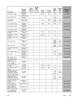
Page 159: ... Delay sec Programmer Defined Settings Engine Functions Critically high fuel level diesel powered models only Fuel Level Critically High 0 100 95 0 10 5 ECM communications loss ECM Comm Err Shutdwn Fixed 10 Not adjustable ECM diagnostics multiple inputs ECM xxxxxx Warning Not adjustable ECM diagnostics multiple inputs ECM xxxxxx Shutdwn Not adjustable ECM faults address conflict ECM Addr Err Shutd...

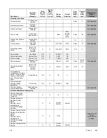
Page 160: ... adjustable Low oil pressure Oil Press Low Shutdwn Fixed Fixed inhibit 5 5 inhibit Not adjustable No coolant temperature signal Temp Sig Loss Shutdwn Not adjustable No oil pressure signal Press Sig Loss Shutdwn Fixed 5 Not adjustable Overcrank Over Crank Shutdwn Fixed 30 inhibit Not adjustable Speed sensor fault Spd Sens Flt Warning Not adjustable General Functions Alarm silence 0 Auto only NFPA 1...

Page 161: ...ay active Eng Cooldown Notice Not adjustable Engine start delay active Start Delay Notice Not adjustable Engine started Engine Start Status Not adjustable Engine stopped Engine Stop Status Not adjustable EPS supplying load Emerg Pwr On Notice Not adjustable File system error controller fault File Error Shutdwn Not adjustable Generator running Gen Running Notice Not adjustable Input output optional...

Page 162: ...tem frequency System Freq DS S 50 60 60 System voltage System Volt DS S 110 600 208 Underfrequency Frequency Low Shutdwn 80 95 90 Fixed 10 ST 60 LT Not adjustable Undervoltage each phase Volts L1 L2 L2 L3 or L3 L1 Low Shutdwn S A 70 95 80 5 30 10 Voltage phase configuration 0 Single phase 1 Single Phase dogleg 2 three phase wye 3 three phase delta SystemPhase DS S 0 3 2 Voltage regulator average v...

Page 163: ...h Charger Custom Profile enabled Charger Maximum Bulk Time Threshold Min S A 60 600 480 Adjustable with Charger Custom Profile enabled Charger Refresh Charge Cycle Time Hr S A 0 23 672 335 Adjustable with Charger Custom Profile enabled Charger Return To Bulk State Voltage Threshold V S A 10 13 12 V 20 26 24 V 12 8 12 V 25 6 24 V Charger Starter Battery Topology Note Verify that the battery topolog...

Page 164: ... 14 16 12 V 28 32 24 V Adjustable with Charger Custom Profile enabled Charger Voltage Float V S A 13 14 12 V 26 28 24 V 13 25 12 V 26 5 24 V Adjustable with Charger Custom Profile enabled Current transformer ratio S S 1 1200 ECM power S S 0 1 0 0 600 300 Engine cooldown delay S A 10 30 15 Engine cyclic crank on S A 1 60 15 Engine cyclic crank pause S A 0 300 0 Engine ECM start delay S A 0 60 60 En...

Page 165: ...ulator volts per Hertz cutin frequency S R 42 62 57 5 Some functions require optional input sensors or are engine ECM dependent on some generator set models ECM inputs are engine manufacturer dependent Changeable only by resetting the controller with a personality profile SiteTech 1 4 or higher Denotes the default parameter range Typically ranges for the NiCad battery topology are slightly wider F...

Page 166: ... states that power is equal to the voltage squared divided by the impedance As the voltage is reduced the power delivered by the alternator decreases by a squared relationship Since it is the power in the alternator that translates into engine torque the engine load is also reduced By changing various parameters of this compensation technique the controlling system can be tailored to match the per...

Page 167: ... uncommon today as most alternators are designed to produce balanced equal voltage on all three phases If the loads applied to the generator set including no load are equal and balanced the output voltage on each phase will be nearly equal However in some applications individual phases may have unequal or unbalanced loads In these cases the output voltages will not be equal on each phase In genera...

Page 168: ...ES A NO entry will turn the feature off and the display will show ENABLED NO The underfrequency unload defaults to an enabled ON condition Frequency Setpoint The frequency setpoint is the cut in point for underfrequency unloading At any operating frequency below the frequency setpoint the output voltage will be reduced The frequency may be entered with resolution to tenths of a Hz The range of acc...

Page 169: ...f time at which current is over the rating is inversely related to the amount of current above the nominal rating In other words the higher the current the shorter the acceptable time The current and time limits are defined by actual test data and are maintained in the personality parameter file Although the equation for detecting a fault is proprietary some of the important limits are shown below...

Page 170: ...er and model Kohler Diesel KDI M TM Kohler Diesel KDI TCR Kohler Gas KG2204 KG2204T GM PSI and Kohler Gas KG6208 KG6208T DD MTU Doosan John Deere Volvo Intake air pressure S D D Intake air Temperature D D S D D D D Coolant level D D D D D D Coolant temperature D C S D C S D C S D C S D C S D C S D Crankcase pressure D ECM battery voltage S S D S S S Engine model number S S S S S S S Engine serial ...

Page 171: ......

Page 172: ...al Instructions English 2010 Kohler Co All rights reserved KOHLER CO Kohler Wisconsin 53044 Phone 920 457 4441 Fax 920 459 1646 For the nearest sales service outlet in the US and Canada phone 1 800 544 2444 KOHLERPower com ...

Reviews: