46
TP-6694
9/20
CONTROLLER OFF position. When the generator set is the prime power mode, all controller functions including the digital
display, LEDs, alarm horn, and communications are inoperative.
2.4.2
Stopping (User Stopping and Fault Shutdown)
Normal Stopping
Run the generator set without load for 5 minutes to ensure adequate engine cooldown.
The controller has a programmable cooldown timer that functions only when the master control button is in the AUTO mode.
To stop the generator set, press the generator set master control OFF/RESET button and wait until the generator set comes to
a complete stop.
Note:
The cooldown cycle times out before the generator set stops when a remote switch or automatic transfer switch initiates the
generator set start/stop sequence.
Emergency Stopping
Use the controller emergency stop switch or optional remote emergency stop for immediate shutdown.
The emergency stop switch bypasses the time delay engine cooldown and immediately shuts down the generator set.
Note:
Use the emergency stop switch(es) for emergency shutdowns only. Use the generator set master control OFF/RESET button
for normal shutdowns.
The controller fault lamp lights and the unit shuts down when the local or remote emergency stop switch activates.
2.4.3
Emergency Stop Switch Resetting
Use the following procedure to reset the generator set after shutdown by a local or remote emergency stop switch. Refer to the
section titled: Controller Resetting procedure, to restart the generator set following a fault shutdown.
1. Investigate and correct the cause of the emergency stop.
2. Reset the optional remote emergency stop switch by replacing the glass piece, when equipped. Additional glass rods
are available as a service part. Reset the controller emergency stop switch by pulling the switch dial outward.
3. Press the generator set master control OFF/RESET button.
4. After resetting all faults using the controller reset procedure in the section titled: Controller Resetting, press the
generator set master control RUN or AUTO button to restart the generator set. The generator set will not crank until the
reset procedure completes.
2.4.4
System Status Lamps
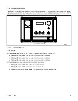
The (OFF/RESET- AUTO- RUN) master control buttons indicate the status condition with an integrated lamp at the button.
The green lamp illuminates on the master control AUTO (automatic start) button indicating the system senses no faults and the
unit is ready to start by remote command.
The red lamp illuminates on the master control OFF/RESET button indicating the generator set is stopped.
The yellow lamp illuminates on the master control RUN button indicating the generator set is cranking or running from a local
command.
Only one of the three master control button lamps will illuminate at any given time.
2.4.5
System Fault Warning Lamp with Digital Displays
The system FAULT lamp glows yellow and the alarm horn sounds indicating a warning fault but does not shut down the generator
set. The fault lamp illuminates yellow and the alarm horn sounds when the fuel tank level on diesel-fueled models approaches
Summary of Contents for APM402
Page 6: ...6 TP 6694 9 20 ...
Page 16: ...16 TP 6694 9 20 ...
Page 42: ...42 TP 6694 9 20 ...
Page 78: ...78 TP 6694 9 20 ...
Page 112: ...112 TP 6694 9 20 ...
Page 120: ...120 TP 6694 9 20 ...
Page 124: ...124 TP 6694 9 20 Figure 54 20 150 kW Permanent Magnet Single Phase Alternators ADV 5875AB 1 ...
Page 125: ...TP 6694 9 20 125 Figure 55 20 300 kW Permanent Magnet Alternators ADV 5875AB 2 ...
Page 128: ...128 TP 6694 9 20 ...
Page 131: ...TP 6694 9 20 131 Figure 61 Battery Charger to Controller Connections DEC 3000 Controller ...
Page 153: ...TP 6694 9 20 153 Figure 90 Controller Wiring Connections GM78246G 1 ...
Page 154: ...154 TP 6694 9 20 Figure 91 Controller Wiring Connections GM78246G 2 ...
Page 171: ......


