-3-
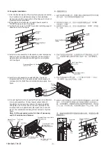
4. Install air pump assembly to faceplate, connect emergency
flush air hose to outlet pipe in faceplate. Connect output
signal cable and input signal cable together, and tighten
nut. See figure
4.
B: Faceplate Installation
1. After the transformer and the circuit are properly connected,
the in wall tank is installed according to the installation
instructions until the construction of the false wall in front of
the water tank is completed.
2. When tighten four locknuts on support board, adjust to
"OPEN" mark as shown. See figure
3. Tighten four screws to "LOCK" mark after installing support
board as shown. See figure
B
1.
2.
OPEN
3.
LOCK
Supporting Board
Locknut
Fixing Lock
Supporting Board
Locknut
Emergency Flush Air Hose
Input Signal Cable
Input Signal Cable
Rib A
A
Slot A
A
Slot B
B
Rib B
B
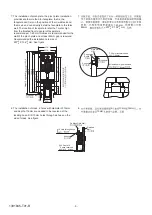
5. Install air pump assembly needs attention: the slot of
faceplate and the rib of air pump needs install properly to
correspond. (A-A/B-B) Prevent installation improperly. See
figure
6. Connect big flush air hose and half flush hose to outlet joint
in air pump assembly. Connect power output cable of
transformer and power input cable of faceplate together,
and tighten nut. Put the lock on the cover directly on the
reversed lock on support board, then push the cover and
lock it. The installation shall begin from bottom to top. See
figure
Note: Cut the excessive parts of air hose if necessary
and fix it onto the tank fastener.
5.
A-A/B-B
6.
Half Flush
Full Flush
Manual Flush
Transformer Power
Output Cable
Faceplate Power Input Cable
Full Flush Air Hose
Half Flush Air Hose
Faceplate
Lock
Supporting Board
Faceplate
1331845-T01-B


