TP-6865 4/14
37
Section 6 Accessories
6.5
Heater
An anti-condensation heater kit is available. The strip
heater is controlled by a hygrostat to raise the
temperature inside the enclosure above the dew point to
prevent condensation.
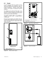
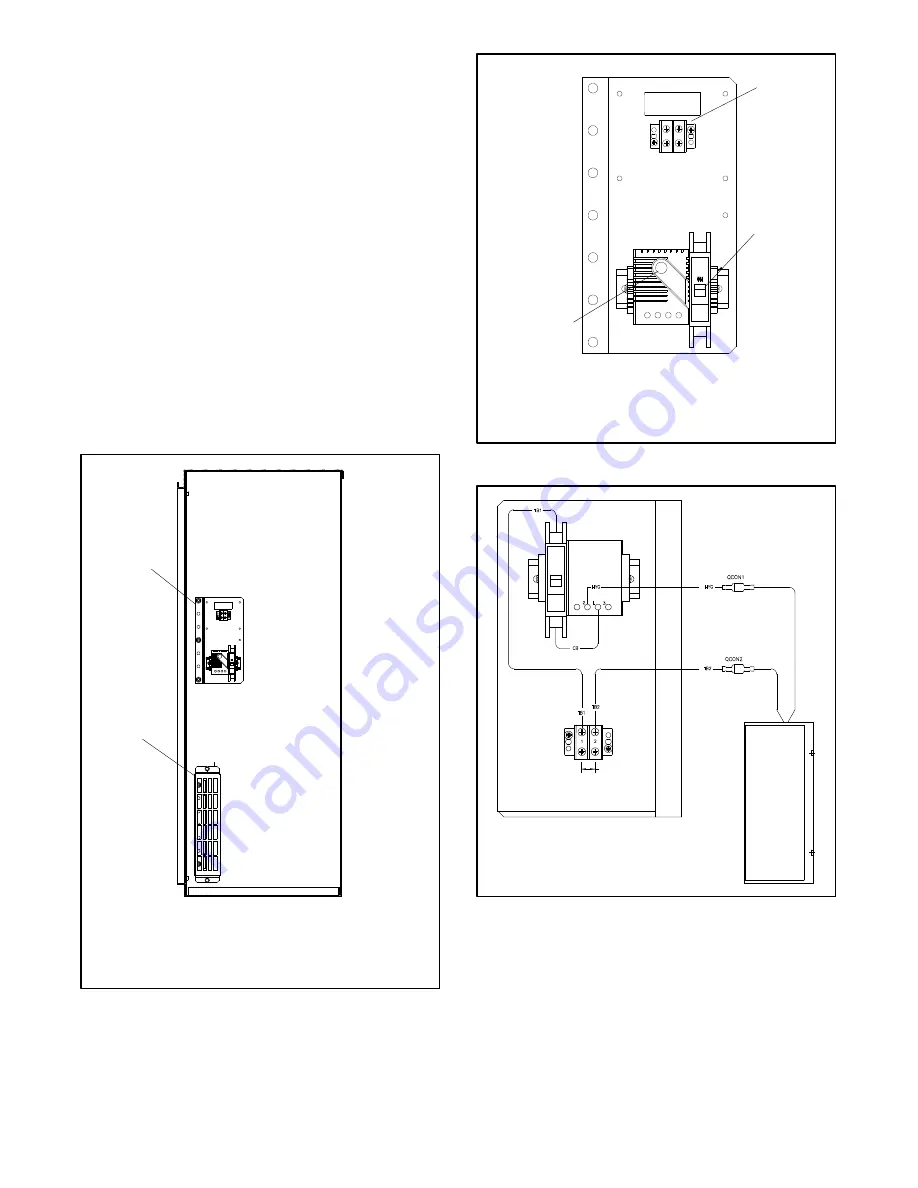
Figure 6-4 shows typical
locations of the heater kit components inside the
enclosure.
The installer must connect 120 VAC power to the
terminal block near the hygrostat. See Figure 6-5 and
Figure 6-6. The heater and hygrostat are connected to
power through a 15-amp circuit breaker.
The relative humidity setting on the hygrostat is
adjustable from 35% to 95%. A setting of 65% is
recommended.
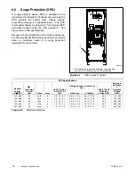
Because of space limitations in the smaller enclosures,
40--225 Amp Model KSS transfer switches can include
either an enclosure heater or a surge protection device
(SPD), but not both.
1. Hygrostat assembly, see Figure 6-5
2. Strip heater with guard
1
GM69824
2
Right Side View
Figure 6-4
Heater Location, Typical
1. 120 VAC power connection terminal block
2. Circuit breaker
3. Relative humidity adjustment control
GM71056
3
2
1
Figure 6-5
Hygrostat Assembly, Typical
GM71278
HYGROSTAT
HEATER
CIRCUIT
BREAKER
TERMINAL
BLOCK
120 VAC ONLY
CUSTOMER SUPPLIED
Figure 6-6
Heater Connections
Summary of Contents for Decision-Maker MPAC 750
Page 2: ......
Page 30: ...TP 6865 4 14 30 Section 4 Communications Notes ...
Page 39: ...TP 6865 4 14 39 Section 6 Accessories Figure 6 9 SPD Wiring Diagram GM89992 ...
Page 42: ...TP 6865 4 14 42 Section 6 Accessories Notes ...
Page 45: ...TPMPFP 6865 4 14 45 Notes ...
Page 46: ...TPMPFP 6865 4 14 46 Notes ...
Page 47: ......

