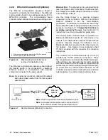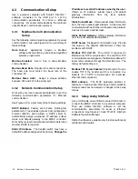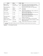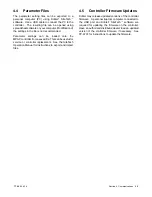
TP-6865 4/14
38
Section 6 Accessories
6.6
Surge Protection (SPD)
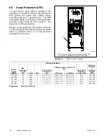
A surge protection device (SPD) is available for the
transfer switch. Installed on the Normal source side, the
SPD protects the system from voltage surges,
preventing damage to household loads. The SPD
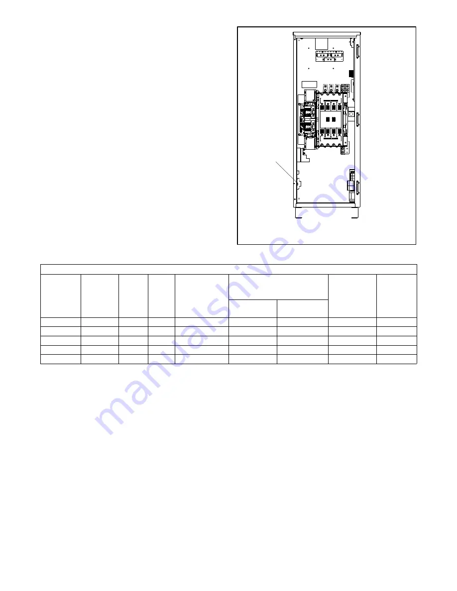
resets automatically. See Figure 6-7 for the typical SPD
assembly location inside the ATS enclosure. See
Figure 6-8 for SPD specifications.
Because of space limitations in the smaller enclosures,
40--225 Amp Model KSS transfer switches can include
either an enclosure heater or a surge protection
device(SPD), but not both.
1
GM49947
1. SPD assembly is typically located on the side of the
enclosure. Location varies for different models.
Figure 6-7
SPD Location, Typical
SPD Specifications
Nominal
Voltage
(V
±
15%)
Max.
Discharge
Current
(kA)
Phase
Poles
UL VPR 3rd Ed
(L-N/N-G/L-G)
(kV)
Limiting Voltage, (L-N/N-G/L-G)
(kV)
Short Circuit
Withstand
Current (kA)
Maximum
Continuou
s
Operating
Voltage
(VAC)
at 3kAmps
at 10kAmp
120 / 240
40
Split
3
0.6 / 1.2 / 0.7
0.6 / 0.4 / 0.6
0.8 / 0.7 / 0.8
200
175 / 350
120 / 208
40
Wye
4
0.6 / 1.2 / 0.7
0.6 / 0.4 / 0.6
0.8 / 0.7 / 0.8
200
175 / 350
277 / 480
40
Wye
4
1.0 / 1.2 / 1.1
1.0 / 0.4 / 1.0
1.2 / 0.7 / 1.2
200
320 / 460
120 / 240
40
HLD
4
1.0 / 1.2 / 1.1
1.0 / 0.4 / 1.0
1.2 / 0.7 / 1.2
200
320 / 460
347 / 600
40
Wye
4
1.3 / 1.2 / 1.4
1.3 / 0.4 / 1.3
1.5 / 0.7 / 1.5
200
440 / 880
Figure 6-8
SPD Specifications
Summary of Contents for Decision-Maker MPAC 750
Page 2: ......
Page 30: ...TP 6865 4 14 30 Section 4 Communications Notes ...
Page 39: ...TP 6865 4 14 39 Section 6 Accessories Figure 6 9 SPD Wiring Diagram GM89992 ...
Page 42: ...TP 6865 4 14 42 Section 6 Accessories Notes ...
Page 45: ...TPMPFP 6865 4 14 45 Notes ...
Page 46: ...TPMPFP 6865 4 14 46 Notes ...
Page 47: ......

