background image

TP-6865 4/14

Appendix 43

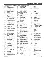
Appendix A Abbreviations

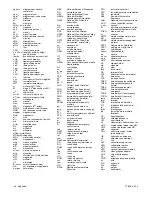
The following list contains abbreviations that may appear in this publication.

A, amp

ampere

ABDC

after bottom dead center

AC

alternating current

A/D

analog to digital

ADC

advanced digital control;

analog to digital converter

adj.

adjust, adjustment

ADV

advertising dimensional

drawing

Ah

amp-hour

AHWT

anticipatory high water

temperature

AISI

American Iron and Steel

Institute

ALOP

anticipatory low oil pressure

alt.

alternator

Al

aluminum

ANSI

American National Standards

Institute (formerly American

Standards Association, ASA)

AO

anticipatory only

APDC

Air Pollution Control District

API

American Petroleum Institute

approx.

approximate, approximately

APU

Auxiliary Power Unit

AQMD

Air Quality Management District

AR

as required, as requested

AS

as supplied, as stated, as

suggested

ASE

American Society of Engineers

ASME

American Society of

Mechanical Engineers

assy.

assembly

ASTM

American Society for Testing

Materials

ATDC

after top dead center

ATS

automatic transfer switch

auto.

automatic

aux.

auxiliary

avg.

average

AVR

automatic voltage regulator

AWG

American Wire Gauge

AWM

appliance wiring material

bat.

battery

BBDC

before bottom dead center

BC

battery charger, battery

charging

BCA

battery charging alternator

BCI

Battery Council International

BDC

before dead center

BHP

brake horsepower

blk.

black (paint color), block

(engine)

blk. htr.

block heater

BMEP

brake mean effective pressure

bps

bits per second

br.

brass

BTDC

before top dead center

Btu

British thermal unit

Btu/min.

British thermal units per minute

C

Celsius, centigrade

cal.

calorie

CAN

controller area network

CARB

California Air Resources Board

CAT5

Category 5 (network cable)

CB

circuit breaker

CC

crank cycle

cc

cubic centimeter

CCA

cold cranking amps

ccw.

counterclockwise

CEC

Canadian Electrical Code

cert.

certificate, certification, certified

cfh

cubic feet per hour

cfm

cubic feet per minute

CG

center of gravity

CID

cubic inch displacement

CL

centerline

cm

centimeter

CMOS

complementary metal oxide

substrate (semiconductor)

com

communications (port)

coml

commercial

Coml/Rec Commercial/Recreational

conn.

connection

cont.

continued

CPVC

chlorinated polyvinyl chloride

crit.

critical

CSA

Canadian Standards

Association

CT

current transformer

Cu

copper

cUL

Canadian Underwriter’s

Laboratories

CUL

Canadian Underwriter’s

Laboratories

cu. in.

cubic inch

cw.

clockwise

CWC

city water-cooled

cyl.

cylinder

D/A

digital to analog

DAC

digital to analog converter

dB

decibel

dB(A)

decibel (A weighted)

DC

direct current

DCR

direct current resistance

deg.,

degree

dept.

department

dia.

diameter

DI/EO

dual inlet/end outlet

DIN

Deutsches Institut fur Normung

e. V. (also Deutsche Industrie

Normenausschuss)

DIP

dual inline package

DPDT

double-pole, double-throw

DPST

double-pole, single-throw

DS

disconnect switch

DVR

digital voltage regulator

E

2

PROM, EEPROM

electrically-erasable

programmable read-only

memory

E, emer.

emergency (power source)

ECM

electronic control module,

engine control module

EDI

electronic data interchange

EFR

emergency frequency relay

e.g.

for example (

exempli gratia)

EG

electronic governor

EGSA

Electrical Generating Systems

Association

EIA

Electronic Industries

Association

EI/EO

end inlet/end outlet

EMI

electromagnetic interference

emiss.

emission

eng.

engine

EPA

Environmental Protection

Agency

EPS

emergency power system

ER

emergency relay

ES

engineering special,

engineered special

ESD

electrostatic discharge

est.

estimated

E-Stop

emergency stop

etc.

et cetera (and so forth)

exh.

exhaust

ext.

external

F

Fahrenheit, female

FHM

flat head machine (screw)

fl. oz.

fluid ounce

flex.

flexible

freq.

frequency

FS

full scale

ft.

foot, feet

ft. lb.

foot pounds (torque)

ft./min.

feet per minute

ftp

file transfer protocol

g

gram

ga.

gauge (meters, wire size)

gal.

gallon

gen.

generator

genset

generator set

GFI

ground fault interrupter

GND,

ground

gov.

governor

gph

gallons per hour

gpm

gallons per minute

gr.

grade, gross

GRD

equipment ground

gr. wt.

gross weight

H x W x D height by width by depth

HC

hex cap

HCHT

high cylinder head temperature

HD

heavy duty

HET

high exhaust temp., high

engine temp.

hex

hexagon

Hg

mercury (element)

HH

hex head

HHC

hex head cap

HP

horsepower

hr.

hour

HS

heat shrink

hsg.

housing

HVAC

heating, ventilation, and air

conditioning

HWT

high water temperature

Hz

hertz (cycles per second)

IBC

International Building Code

IC

integrated circuit

ID

inside diameter, identification

IEC

International Electrotechnical

Commission

IEEE

Institute of Electrical and

Electronics Engineers

IMS

improved motor starting

in.

inch

in. H

2

O

inches of water

in. Hg

inches of mercury

in. lb.

inch pounds

Inc.

incorporated

ind.

industrial

int.

internal

int./ext.

internal/external

I/O

input/output

IP

internet protocol

ISO

International Organization for

Standardization

J

joule

JIS

Japanese Industry Standard

k

kilo (1000)

K

kelvin

kA

kiloampere

KB

kilobyte (2

10

bytes)

KBus

Kohler communication protocol

kg

kilogram

Summary of Contents for Decision-Maker MPAC 750

Page 1: ...Automatic Transfer Switches Controls Decision Makerr MPAC 750 Transfer Switch Model KSS TP 6865 4 14a Operation ...

Page 2: ......

Page 3: ... 1 8 Controller Reset 14 1 8 1 Reboot 14 1 8 2 Reset to Default Settings 14 Section 2 Sequence of Operation 15 2 1 Controller Power up Reset 15 2 2 Sequence of Operation 15 2 2 1 Source N Loss and Return 15 2 2 2 Exerciser Operation 15 2 2 3 Test Sequence 16 Section 3 Settings 17 3 1 Introduction 17 3 2 System Setup 17 3 3 System Parameters 17 3 3 1 Transition Type Standard 17 3 3 2 Commit to Tran...

Page 4: ...Generator Set Exercise 32 5 2 2 Monthly Automatic Control System Test 32 5 3 Inspection and Service 33 5 3 1 General Inspection 33 5 3 2 SPD Inspection 33 5 3 3 Other Inspections and Service 33 5 4 Service Schedule 34 Section 6 Accessories 35 6 1 Introduction 35 6 2 Controller Disconnect Switch 35 6 3 Ethernet Board 36 6 4 Programmable Exerciser 36 6 5 Heater 37 6 6 Surge Protection SPD 38 6 6 1 S...

Page 5: ...ING Disabling the generator set Accidental starting can cause severe injury or death Before working on the generator set or connected equipment disable the generator set as follows 1 Move the generator set master switch to the OFF position 2 Disconnect the power to the battery charger 3 Remove the battery cables negative lead first Reconnect the negative lead last when reconnecting the battery Fol...

Page 6: ...ck deenergize the normal power source before making any line or auxiliary connections Servicing the transfer switch controls and accessories within the enclosure Hazardous voltage can cause severe injury or death Disconnect the transfer switch controls at the inline connector to deenergize the circuit boards and logic circuitry but allow the transfer switch to continue to supply power to the load ...

Page 7: ... Obtain service from an authorized service distributor dealer to keep equipment in top condition Read this manual and carefully follow all procedures and safety precautions to ensure proper equipment operation and to avoid bodily injury Read and follow the Safety Precautions and Instructions section at the beginning of this manual Keep this manual with the equipment for future reference List of Re...

Page 8: ...rope Middle East Africa EMEA Kohler Power Systems Netherlands B V Kristallaan 1 4761 ZC Zevenbergen The Netherlands Phone 31 168 331630 Fax 31 168 331631 Asia Pacific Power Systems Asia Pacific Regional Office Singapore Republic of Singapore Phone 65 6264 6422 Fax 65 6264 6455 China North China Regional Office Beijing Phone 86 10 6518 7950 86 10 6518 7951 86 10 6518 7952 Fax 86 10 6518 7955 East C...

Page 9: ...d Source Eis the standby generator set The engine start contacts are associated with Source E The Preferred Source is the source that will be used if both sources are available With the MPAC 750 controller the preferred source is Source N The standby source is Source E 1 3 User Interface Panel The user interface panelislocated on the transfer switch door Figure 1 1 shows the user interface pushbut...

Page 10: ...c 2 sec Flash 0 5 sec 2 sec Figure 1 3 Test and Exercise Indication 1 4 Test Use the Test button to D Start and run the generator set unloaded test D Simulate a Source N failure resulting in a transfer to Source E loaded test If the emergency source is lost during a system test the test is terminated If the contactor is in the standby position it transfers immediately to the preferred position For...

Page 11: ...fer to Section 2 2 3 for a more detailed description of the test sequence of operation Note If the standby source fails during a loaded test the ATS will immediately attempt to transfer to the preferred source Automatic Operation Test Procedure 1 Check the controller LED indicators to verify that the Source N Position and Source N Available indicators are lit 2 Verify that the generator set master...

Page 12: ...d runs the generator set for 20 minutes without transferring the load Press and hold the exercise button for 3 5 seconds to start an unloaded exercise During an unloaded exercise the Source E available LED flashes 0 5 seconds on and 2 seconds off 1 6 3 Loaded Exercise A loaded exercise starts the generator set and transfers the load from the normal source to Source E Press and hold the Exercise bu...

Page 13: ...e controller and normal ATS operation continues Condition Type Description Failure to Acquire Standby Source Warning The source voltage did not reach the acceptable range within a set time see Time Delays For example the Source E generator set did not start IPM Synching In Phase Monitor Synching Warning status The two sources did not come into phase within the Fail to Synchronize time delay Note I...

Page 14: ...ds 1 8 2 Reset to Default Settings A personal computer with Kohlerr SiteTecht software can be used to reset the controller to factory defaults if necessary SiteTech software is only available to Kohler authorized distributors or dealers Note Resetting to the default parameters will reset all parameters including the system voltage and frequency to a factory default setting The default system volta...

Page 15: ...nd the contactor is already in the preferred position the engine start contacts open immediately bypassing the engine cooldown time delay 2 2 Sequence of Operation The Sequence of Operation describes the transfer switch normal operation The MPAC 750 controller operates using standard transition only no programmed or closed transition operation Operation can be affected by faults such as the normal...

Page 16: ...e start contacts open signaling the generator to stop 2 2 3 Test Sequence Unloaded Test Function is Initiated 1 The generator set is signaled to start 2 The generator starts and Source E becomes available Unloaded Test Function is Ended 1 Engine cooldown time delay expires 2 The generator is signaled to stop Loaded Test Function is Initiated 1 The generator is signaled to start engine start contac...

Page 17: ...late 3 3 System Parameters The transfer switch is factory set for the transfer switch model and rating System parameters should not require adjustment The system parameter factory settings are shown in Figure 3 1 Note that some settings are not adjustable System Parameter Factory Setting Transition type standard See the ATS nameplate Single three phase Operating voltage Operating frequency 50 or 6...

Page 18: ... 3 3 The engine start time delay and transfer time delays can prevent nuisance transfers caused by brief voltage dips or surges The engine cooldown time delay holds the engine start contacts closed for a designated time after transfer to allow the generator set to run without load before shutting down If the standby source does not reach acceptable voltage and stabilize within the allowed time the...

Page 19: ... The optional programmable exerciser uses the remote test input See the instructions provided with the exerciser for more information Programmable Inputs LED LED Inhibit Transfer maintenance mode None Flashing Remote Common Alarm Steady None Remote Test None None Figure 3 4 Available Programmable Inputs 3 6 2 Output Functions Output functions are shown in Figure 3 5 Information about selected outp...

Page 20: ...that can be assigned to the common alarm Alarm Descriptions Auxiliary Switch Fault Auxiliary Switch Open Contactor in Preferred Contactor in Source E Position Contactor in Source N Position Contactor in Standby Position Exerciser Active Fail to Acquire Standby Source Fail to Transfer In Phase Monitor Synching Not in Auto Remote Common Alarm Source E Available Source N Available Source N Rotation E...

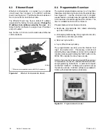
Page 21: ...ntroller can send encapsulated Modbus messages over the network connection Only one Modbus address can be assigned to the controller regardless of the communication port or protocol being used Note Modbusr applications require a Modbus software driver written by a trained and qualified systems programmer 4 2 Connections 4 2 1 USB Port SiteTech Connection A personal computer and Kohler SiteTech sof...

Page 22: ...d pair cable to connect to the RS 485 connectors on controller terminal strip TB2 for serial connections For connection to a PC use a USB to RS 485 converter Connect the Modbus input and output to the terminals shown in Figure 4 4 Use 12 24 AWG shielded twisted pair wire Belden cable 9841 or equivalent is recommended Connect one end of the shield to ground Leave the other end of the shield disconn...

Page 23: ...ting resistor 121 Ohms USB to RS 485 port converter Terminating resistor may be required 121 Ohms In Out In In In Out Out Out PC PC PC Use Belden 9841 or equivalent shielded twisted pair communication cable for RS 485 connections Ground one end of the cable shield Leave the other end of the cable shield disconnected Long cables and high communication speeds will require a terminating resistor Use ...

Page 24: ... default IP address assigned at the factory for test purposes See Figure 4 7 Change the IP address to an address owned by the user See Section 3 8 for instructions to set the communication parameters The transfer switch controller does not operate as a Modbus to Ethernet converter for other devices in a network For multiple device networks connected to the personal computer through the Ethernet us...

Page 25: ... Last device RS 485 Converter Modbusr Ethernet IP xx xx xx 05 RS 485 Modbusr TCP IP Modbusr TCP IP Ethernet Network PC IP xx xx xx 01 Terminating resistor 121 Ohms Device Device RS 485 Device Modbusr RTU RS 485 Modbusr TCP IP Category 5e Modbusr TCP IP Category 5e Figure 4 8 Ethernet Connections to Multiple Device Network ...

Page 26: ... The transfer switch may have a default IP address assigned at the factory Change the IP address to a static IP address owned by the user Obtain an IP address subnet mask and default gateway information from the local network administrator Static Subnet Mask Obtain subnet mask information from the local network administrator All devices that communicate with each other on the same local network mu...

Page 27: ...l network administrator Every device on the network must have a unique IP address Static Subnet Mask See notes Obtain from your local network administrator All devices that communicate with each other on the same local network must use the same subnet mask Static Default Gateway See notes Obtain from your local network administrator DHCP Server Read only Displayed for information only Modbus TCP U...

Page 28: ...TP 6865 4 14 28 Section 4 Communications Obtain from the local network administrator Figure 4 10 Communications Parameters in Kohler SiteTech Software ...

Page 29: ...be loaded onto the MPAC controller froma saved file Thiscan be usefulfor service or controller replacement See the SiteTech Operation Manual for instructions to export and import files 4 5 Controller Firmware Updates Kohler may release updated versions of the controller firmware A personal laptop computer connected to the USB port and Kohlerr SiteTecht software are required for updating the firmwa...

Page 30: ...TP 6865 4 14 30 Section 4 Communications Notes ...

Page 31: ...g can cause severe injury or death Before working on the generator set or connected equipment disable the generator set as follows 1 Move the generator set master switch to the OFF position 2 Disconnect the power to the battery charger 3 Remove the battery cables negative lead first Reconnect the negative lead last when reconnecting the battery Follow these precautions to prevent starting of the g...

Page 32: ...re deenergized Short circuits Hazardous voltage current can cause severe injury or death Short circuits can cause bodily injury and or equipment damage Do not contact electrical connections with tools or jewelry while making adjustments or repairs Remove all jewelry before servicing the equipment NOTICE Electrostatic discharge damage Electrostatic discharge ESD damages electronic circuit boards Pr...

Page 33: ...dition noticed during an external inspection may have affected internal components Contact an authorized distributor dealer to inspect and service the transfer switch if any of the following conditions are found inside the transfer switch D Accumulations of dirt dust moisture or other contaminants D Signs of corrosion D Worn missing or broken components D Loose hardware D Wire or cable insulation ...

Page 34: ...ned and not badly worn 5 3 1 X X X M Inspect the inside of transfer switch for any signs of excessive vibration leakage high temperature contamination or deterioration 5 3 3 D D D Y Check that all internal hardware is in place tightened and not badly worn 5 3 3 X D D Y SPD Modules if equipped Check status indicators 6 6 X D Every 2 months Check condition of connecting leads 6 6 X D Service more fr...

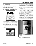
Page 35: ...or set by an automatic transfer switch remote start stop switch or engine start command from a remote computer Hazardous voltage Will cause severe injury or death Only authorized personnel should open the enclosure DANGER The controller disconnect switch allows disconnection of the power to the controller during maintenance and service See Figure 6 1 Note Disable the generator set before using the...

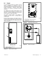
Page 36: ... program weekly loaded or unloaded exercise periods in addition to the exercise time set through the ATS controller The timer is installed inside the ATS enclosure Programmable exerciser features include D Seven day programmable timer allows scheduling up to 56 on off events D LCD display indicates day time program run modes on off status and skip cycle status D Skip next cycle button D 5 year lit...

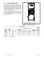
Page 37: ...circuit breaker The relative humidity setting on the hygrostat is adjustable from 35 to 95 A setting of 65 is recommended Because of space limitations in the smaller enclosures 40 225 Amp Model KSS transfer switches can include either an enclosure heater or a surge protection device SPD but not both 1 Hygrostat assembly see Figure 6 5 2 Strip heater with guard 1 GM69824 2 Right Side View Figure 6 ...

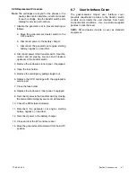
Page 38: ...ice SPD but not both 1 GM49947 1 SPD assembly is typically located on the side of the enclosure Location varies for different models Figure 6 7 SPD Location Typical SPD Specifications Nominal Voltage V 15 Max Discharge Current kA Phase Poles UL VPR 3rd Ed L N N G L G kV Limiting Voltage L N N G L G kV Short Circuit Withstand Current kA Maximum Continuou s Operating Voltage VAC at 3kAmps at 10kAmp ...

Page 39: ...TP 6865 4 14 39 Section 6 Accessories Figure 6 9 SPD Wiring Diagram GM89992 ...

Page 40: ...agram for connections SPD Remote Status Indication Specification Contact rating 1 A 250 VAC Wire Size 16 AWG Figure 6 11 Remote Status Indicator Contact Specifications 6 6 3 SPD Replacement Replace the module when the SPD indicator turns red Follow the replacement procedure in this section Hazardous voltage Will cause severe injury or death This equipment must be installed and serviced by qualifie...

Page 41: ...4 Open the fuse holder 5 Remove the cartridge by pulling straight out 6 Replace the SPD cartridge with the appropriate service part 7 Close the fuse holder 8 Replace the enclosure s inner panel if equipped 9 Reconnect power to the transfer switch by closing the normaland emergencysource circuitbreakers 10 Check the SPD status indicators 11 Reconnect the generator set engine starting battery negati...

Page 42: ...TP 6865 4 14 42 Section 6 Accessories Notes ...

Page 43: ...es cu in cubic inch cw clockwise CWC city water cooled cyl cylinder D A digital to analog DAC digital to analog converter dB decibel dB A decibel A weighted DC direct current DCR direct current resistance deg degree dept department dia diameter DI EO dual inlet end outlet DIN Deutsches Institut fur Normung e V also Deutsche Industrie Normenausschuss DIP dual inline package DPDT double pole double ...

Page 44: ...Phillipsr head Crimptiter screw PHH Phillipsr hex head screw PHM pan head machine screw PLC programmable logic control PMG permanent magnet generator pot potentiometer potential ppm parts per million PROM programmable read only memory psi pounds per square inch psig pounds per square inch gauge pt pint PTC positive temperature coefficient PTO power takeoff PVC polyvinyl chloride qt quart quarts qt...

Page 45: ...TPMPFP 6865 4 14 45 Notes ...

Page 46: ...TPMPFP 6865 4 14 46 Notes ...

Page 47: ......

Page 48: ...ler Wisconsin 53044 Phone 920 457 4441 Fax 920 459 1646 For the nearest sales service outlet in the US and Canada phone 1 800 544 2444 KOHLERPower com Kohler Power Systems Asia Pacific Headquarters 7 Jurong Pier Road Singapore 619159 Phone 65 6264 6422 Fax 65 6264 6455 ...

Reviews: