TT-1303
7/02
7
3.6
GM17071-KP3 and GM17071-KP3S kits only
(450--2000 kW).
Swing the access door closed
and install the screws.
3.7
Replace the junction box panel and hardware.
4.
Select a mounting location for the remote
annunciator panel.
4.1
Select a visible location for mounting the remote
annunciator panel. Install the remote annunciator
panel, either surface- or flush-mounted, in a
location easily observable by operating personnel
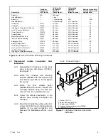
at their work stations. See Figure 8 for remote
annunciator dimensions and mounting hole
dimensions.
4.2
Surface-mount
remote
annunciator
initial
installation.
4.2.1
Prepare the mounting site by drilling pilot
holes for anchors, if used.
Note:
Mount the remote annunciator kit to
a standard 10 cm (4 in.) square
electrical box installed in the wall.
4.2.2
Create an opening in the wall for the
electrical wiring from the 14-relay dry
contact assembly, P and N battery
connections, and transfer switch.
4.2.3
Disassemble the remote annunciator box.
Remove six drill screws to disassemble
the side panels and separate the front and
back remote annunciator panels. Retain
the side panels (287798) and the drill
screws (X-794-2) for reassembly.
4.2.4
Mount the remote annunciator back panel
to the wall or to the electrical box in the
wall. See Figure 8 for the mounting hole
dimensions.
Protect
the
remote
annunciator from dust and debris when
drilling the holes.
Note:
Use mounting hardware suitable for the
wall composition and thickness.
4.2.5
Proceed to step 5, Wire the remote
annunciator.
PREALARM
HIGH ENGINE
TEMPERATURE
PREALARM
LOW OIL
PRESSURE
LOW WATER
TEMPERATURE
LOW FUEL
HIGH ENGINE
TEMPERATURE
LOW OIL
PRESSURE
EMERGENCY
STOP
OVERSPEED
BATTERY
CHARGER FAULT
LOW BATTERY
VOLTAGE
AUXILARY
FAULT
OVERCRANK
LINE
POWER
GENERATOR
POWER
SYSTEM
READY
GENERATOR
SWITCH
NOT IN AUTO
NORMAL
SILENCE
LAMP
TEST
ALARM
42B
35
63
41 40 39 48 38 36 12 26 62 61 58 59 60 80 N
To Annunciator
Contact Box
To Transfer Panel
(Remaining Leads)
(58, 59)
PREALARM
HIGH ENGINE
TEMPERATURE
PREALARM
LOW OIL
PRESSURE
LOW WATER
TEMPERATURE
LOW FUEL
HIGH ENGINE
TEMPERATURE
LOW OIL
PRESSURE
EMERGENCY
STOP
OVERSPEED
BATTERY
CHARGER FAULT
LOW BATTERY
VOLTAGE
AUXILARY
FAULT
OVERCRANK
LINE
POWER
GENERATOR
POWER
SYSTEM
READY
GENERATOR
SWITCH
NOT IN AUTO
NORMAL
SILENCE
LAMP
TEST
ALARM
2.59 [66]
8.32 [211]
13.50 [343]
1.03
[26]
7.44
[189]
9.50
[241]
0.19
[5]
4.62
[1
17]
5.00
[127]
8.69 [221]
2.38 [60]
3.38 [86]
2.66 [68]
3.38
[86]
0.81
[21]
0.219 [6]
4 Holes
4.35 [110]
3.38
[86]
2.11 [54]
4 HOLES
Surface Mount
Flush Mount
ADV-5957-
0.219 [4]
4.62
[1
17]
Note:
This view is shown as seen from the front, with the front panel removed.
Note:
Dimensions in [ ] are millimeter equivalents.
Figure 8
Component Dimensions


