background image

3. Secure the Module to the Stud Framing

CAUTION: Risk of product damage.

Do not lift the whirlpool by the piping or pump, or use the

piping or pump for structural support of the whirlpool.

With help, carefully lift the module into position.

Insert the drain tailpiece into the trap. Make sure the whirlpool is level and resting on all support
blocks.

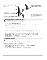
Plumb and level the module along the nailing-in flanges, and use shims to level the module rim. Do
not support the module by the rim.

Place shims under the module body to add support when module is in use.

Drill small pilot holes 8

(20.3 cm) apart through the vertical nailing-in flanges along the front of the

module. Then drill small pilot holes through the horizontal nailing-in flange at each side and back
stud. Add shims between the nailing-in flange and the studs as needed to eliminate gaps.

Nail 1/4

(6 mm) thick furring strips to the studs to shim out to the edge of the nailing-in flange.

For metal stud construction, drill the fastener holes through the nailing-in flange and the metal
studs, and secure with sheet metal screws.

Use #6 large-head galvanized nails to secure the nailing-in flange to the studs.

4. Install the Plumbing

CAUTION: Risk of property damage.

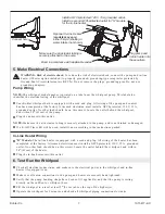
Ensure a watertight seal on the whirlpool drain.

Connect the drain to the trap according to the drain manufacturer’s instructions.

NOTICE:

An access panel will simplify future maintenance.

Install the faucet valving according to the faucet manufacturer’s instructions. Do not install the
faucet trim until instructed. Open the hot and cold water supplies, and check the supply
connections for leakage.

Run water into the whirlpool, and check the drain connections for leakage.

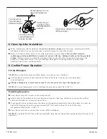
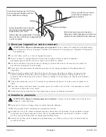
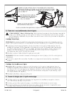
Nail 1/4" (6 mm) thick furring strips 
to shim out to the edge of the 
nailing-in flange.

Drill a small hole through the 
back nailing-in flange at each 
stud.

Place shims under the whirlpool 
body to provide support when the 
whirlpool is in use.

Drill small holes through the side 
nailing-in flange 8" (20.3 cm) apart.

Use #6 large-head galvanized nails to secure 
the side nailing-in flange to the studs.

Stud

Nailing-In Flange

1015417-2-C

6

Kohler Co.

Summary of Contents for K-1630

Page 1: ...th Shower Whirlpool Module M product numbers are for Mexico i e K 12345M Los n meros de productos seguidos de M corresponden a M xico Ej K 12345M Fran ais page Fran ais 1 Espa ol p gina Espa ol 1 K 16...

Page 2: ...ts against line to ground shock hazard Use a 120 V 15 A 60 Hz dedicated service for the whirlpool H models require a separate 120 V 15 A 60 Hz dedicated service for the in line heater NOTE If the supp...

Page 3: ...res 2 Connections and Service Access 2 Thank You For Choosing Kohler Company 4 Tools and Materials 4 Before You Begin 4 Prepare the Site 5 Prepare the Whirlpool 5 Secure the Module to the Stud Framing...

Page 4: ...exterior walls before installation When fire rated wall is specified the stud opening dimensions are to the inside of the wallboard If the module will be installed adjacent to vertical ducts or chases...

Page 5: ...ked Cap the supplies and check for leaks 2 Prepare the Whirlpool Install the drain to the whirlpool according to the drain manufacturer s instructions Do not connect the trap at this time NOTE To enha...

Page 6: ...ction drill the fastener holes through the nailing in flange and the metal studs and secure with sheet metal screws Use 6 large head galvanized nails to secure the nailing in flange to the studs 4 Ins...

Page 7: ...ater is equipped with a cord and plug All wiring of the heater has been completed at the factory A licensed electrician must install a GFCI protected 120 V 15 A grounded outlet No other load should be...

Page 8: ...Test Run the Whirlpool cont For additional information on whirlpool operation refer to Confirm Proper Operation 1015417 2 C 8 Kohler Co...

Page 9: ...tall the finished wall material Install the mixing valve shower and spout trim according to the instructions packed with the trim Install any extra grab bars or towel bars to the bridging previously i...

Page 10: ...pool to a water level at least 2 5 1 cm above the top of the highest jet NOTE The water temperature in the whirlpool should not exceed 104 F 40 C Operating Sequence Press the air actuator to turn on t...

Page 11: ...fully insert the jet into the housing and lightly push and rotate the jet until it snaps into position Do not force the jet NOTE When installed correctly the jet should turn smoothly both clockwise an...

Page 12: ...ce activated D Check for blockage at motor vents Remove blockage and allow motor to cool Check for suction blockage Remove blockage and allow motor to cool Check for jet blockage Remove blockage and a...

Page 13: ...r l installation y compris les conditions suivantes AVIS Respecter tous les codes de plomberie et lectriques locaux Information sur le produit Branchements lectriques requis L installation doit avoir...

Page 14: ...t tre situ tout pr s de la pompe tudier le plan de raccordement qui accompagne la baignoire hydromassage Sommaire Renseignements importants 1 Information sur le produit 1 Branchements lectriques requi...

Page 15: ...parois ext rieures avant l installation Dans le cas d un mur r sistant au feu les dimensions d ouverture dans les montants sont compt es l int rieur du mur Si l appareil doit tre install adjacent des...

Page 16: ...Boucher les alimentations et v rifier s il y a des fuites 2 Pr parer la baignoire hydromassage Installer le drain sur la baignoire hydromassage selon les instructions du fabricant Ne pas connecter le...

Page 17: ...es sur la bride et les montants en m tal et s curiser l aide des vis en m tal Utiliser des clous galvanis s 6 t te large pour s curiser la bride aux montants 4 Installer la plomberie ATTENTION Risque...

Page 18: ...Cabl ge de chauffeau en ligne Mod les H Le chauffeau en ligne est dot d une prise et d un cordon d alimentation Tous les c blages du chauffeau ont t effectu s en usine Un lectricien agr doit installer...

Page 19: ...onctionner la baignoire hydromassage pendant 5 minutes et v rifier que tous les raccords des tuyaux de la baignoire hydromassage n aient pas de fuites Pour plus d information concernant le fonctionnem...

Page 20: ...u mur Installer le mat riau du mur fini Installer le mitigeur la douche et le bec conform ment aux instructions du fabricant Installer les barres d appui et les porte serviettes sur l entretoisement p...

Page 21: ...jet compl tement vers la gauche Remplir la baignoire au moins 2 5 1 cm au dessus du jet le plus lev REMARQUE La temp rature de la baignoire hydromassage ne devrait pas exc der 104 F 40 C S quence d op...

Page 22: ...afin d viter le fonctionnement bruyant du jet Ins rer d licatement le jet dans le logement puis pousser et pivoter l g rement jusqu ce qu il s enclenche en position Ne pas forcer le jet REMARQUE Lors...

Page 23: ...ctiv D V rifier s il y a blocage aux prises d air du moteur Retirer l obstruction et laisser refroidir le moteur V rifier si la conduite d aspiration n est pas bouch e Retirer l obstruction et laisser...

Page 24: ...cluyendo los requisitos detallados a continuaci n AVISO Cumpla con todos los c digos locales de electricidad y de plomer a Informaci n sobre el producto Requisitos el ctricos La instalaci n debe conta...

Page 25: ...iagrama de instalaci n incluido con la ba era de hidromasaje Contenido Informaci n importante 1 Informaci n sobre el producto 1 Requisitos el ctricos 1 Advertencias 1 Componentes montados en f brica 2...

Page 26: ...ci n Evite doblar las paredes laterales para no ocasionar da os al m dulo A sle todas las paredes exteriores antes de la instalaci n Cuando se especifique que la pared sea resistente al fuego las dime...

Page 27: ...os que imitan azulejos preste especial atenci n al emplazamiento de las conexiones expuestas de plomer a Trate de colocar las v lvulas y las conexiones de la ducha en lugares en los que se complemente...

Page 28: ...re la ba era de hidromasaje Instale el desag e en la ba era de hidromasaje seg n las instrucciones del fabricante No conecte el sif n en este momento NOTA Para mejorar el aspecto de los m dulos con di...

Page 29: ...a trav s del reborde de clavado y de los postes de metal y fije con tornillos de metal Utilice clavos grandes galvanizados del n 6 para fijar el reborde de clavado a los postes 4 Instalaci n de plome...

Page 30: ...temporizador K 1639 inst lelo ahora conforme a las instrucciones incluidas Cableado del calentador en l nea Modelos H El calentador en l nea est equipado de un cable y un enchufe Todo el cableado del...

Page 31: ...ra de hidromasaje Llene la ba era de hidromasaje al menos 2 5 1 cm por encima del inyector m s alto Deje funcionar la ba era de hidromasaje durante 5 minutos revise todas las conexiones de las tuber a...

Page 32: ...terial de la pared acabada Instale la v lvula mezcladora la ducha la guarnici n del surtidor seg n las instrucciones incluidas Instale cualquier agarradera o toallero adicional en los puntales de refu...

Page 33: ...ne la ba era de hidromasaje al menos 2 5 1 cm por encima del inyector m s alto NOTA La temperatura del agua en la ba era de hidromasaje no debe exceder de 104 F 40 C Secuencia de funcionamiento Presio...

Page 34: ...anillo O ring con lubricante de silicona para evitar que el inyector haga ruido Inserte el inyector en el alojamiento con cuidado empuje y gire el inyector levemente hasta que se encaje en su lugar No...

Page 35: ...otor se ha recalentado activando el dispositivo de protecci n D Verifique que las ventilaciones del motor no est n tapadas Elimine la obstrucci n y permita que el motor se enfr e Verifique que la succ...

Page 36: ...USA 1 800 4 KOHLER Canada 1 800 964 5590 M xico 001 877 680 1310 kohler com 2004 Kohler Co 1015417 2 C...

Reviews: